Как выбрать гостиницу для кошек
14 декабря, 2021
During the conceptual and preliminary design phases it was proven that polymeric materials offered good structural advantages and various designs using polymeric materials were considered and evaluated.
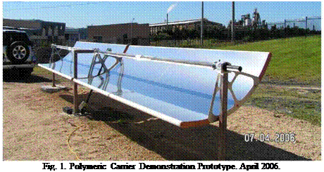 |
In the initial prototype (which was developed purely as a demonstrator) the structure providing and supporting the parabolic shape was intended to take the entire load on the collector. Refer to Figure 1.
During the detailed development phase it was proven that a large volume of polymeric foam material with a layer of structural skin could provide the structural integrity required. Various polymeric foam materials and structural skin materials were investigated for this purpose. Many previous attempts in manufacturing concentrating collectors using polymeric materials have failed due to the lack of long term form stability of many polymeric core materials. Form stable polymeric core materials do exist but are very expensive in volume. The concept was abandoned due to the high cost.
With a focus on reduced overall cost, a final configuration was devised whereby each component in the system had a specific objective, and the optimum geometry for each component was chosen. This lead to the choice of a single torque tube with sufficient stiffness to carry the torsional loads of the system, and a simple sandwich panel rigidly mounted to the torque tube which would provide sufficient bending stiffness to maintain the parabolic mirror surface. Mounting arms for the receiver tube were to be mounted directly on the torque tube, and the torque tube itself would also function as the rotation shaft of the system. The possibility of counter balancing the system was
also analysed and found to be cost effective as it reduced the torsional load on the system which improved the system optical performance.
This resulting system has a relatively low surface area to be laid up, has sufficiently thin core material that pre-forming the core would be reduced or eliminated, and can be packed efficiently for shipping. Furthermore, the system is readily scalable, can be produced in modules, and can utilise standard off the shelf components for mountings, shafts, bearings. On site assembly of components, and reduced component weight were also favourable, and the system also allowed for reduction of the gap between panels adjacent to the actuation cylinder.
The team developed a unique technique to form and bond the reflector (speciality aluminium mirror using physical vapour deposition (PVD) to obtain the reflectivity or speciality silvered glass mirrors) to a structural carrier in a one step manufacturing process using composite materials. The carrier consists of an efficient sandwich structure of fibre-reinforced polymeric skins and a specialised core material. Furthermore due to the excellent bond between the carrier and the mirror, the mechanical properties of the mirror are integrated into the strength and stiffness of the carrier. This process results in a lightweight, stiff and accurate surface. The use of specialised materials also provides a form stable carrier, overcoming problematic creep experienced when using low cost inferior core materials and manufacturing techniques.
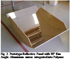 |
After a number of iterations with processes and materials the team successfully manufactured small prototype reflective panels with a 90° rim angle (RA) as shown in Figure 2.
Finite element (FE) analysis of the 90° rim angle collector was undertaken which considered representative wind loads that induce bending and torque. The analysis was based on 12m/s wind speed with allowable deflection limited to 0.5° over a 10m representative trough length.
Remaining torque and bending moment loads were considered to be born by the steel torque tube/counter-weight combination as opposed to the shell and thus could be excluded.
The optimum core thickness for the composite sandwich laminate of the PTC shell was calculated to be approximately 6mm. The design called for vacuum resin infusion processing of the laminate. This was first employed on the 90° RA prototypes. Commercially available core of 10mm thickness combining a grooving pattern on its surface for vacuum resin infusion was sourced.
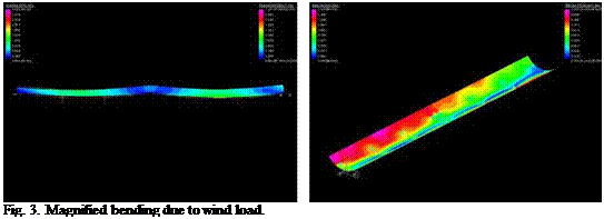 |
When a subsequent decision was made to open up the rim angle to a flatter 50 degrees due to receiver re-design, the10mm core thickness choice proved useful by offsetting the reduction in stiffness caused by the reduced shell curvature and obviated the need for further FE analysis. Subsequent field trials of the manufactured prototypes confirmed this course of action. Representative FE plots of the 90 degree RA geometry are illustrated in Figures 3 and 4, firstly for magnified bending and then for magnified torque (twisting).
Fig. 4. Magnified twist due to wind load.
Several subtle but significant composite laminate modifications were evaluated in the numerical modeling and on the physical 90° RA prototypes before settling on the chosen lamination sequence. The laminate schedule features the aluminium mirror surface on the mould side which is also considered structurally effective, combined with a composite sandwich laminate.
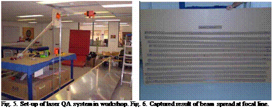 |
After the completion of the first of these full size reflective panels the team developed a laser measuring QA procedure to record the focal accuracy. The set-up of the laser is shown in Figure 5 and the results in Figure 6. This yielded pleasing results and generated the confidence to proceed with the remaining 7 prototype reflective panels.
To complete the design of the collector full 3D modelling and documentation of not only the parabolic reflector but also the associated steel componentry comprising the torque tube, bearings, drive system, receiver mountings, mounting legs and counter-weights etc. was conducted. This design step involved several iterations to reduce cost. The solar tracking system was developed in house and consists of a stepper motor driving through a reduction system and an extremely accurate inclinometer mounted directly on the collector. The system is controlled with a
proprietary embedded microcontroller and solar tracking algorithm. All components are sized to be economically packed into ISO shipping containers for transport and can be manually handled and easily installed on site
2.
 |
Key characteristics of the collector are
• 1.2 m Aperture by 6 m long parabolic panel elements.
• 4 panels per “standard” module — 24 m long modules.
• Torque tube is rotational axis.
• Counterweight balanced
• 50° rim angle chosen to suit a new shrouded receiver under development.
• Non-evacuated glass encased 25.4 mm stainless steel receiver with selective coating.
• 45:1 geometric concentration ratio.
• Expected maximum temp 220° C
The first test conducted on the collector was a photogrammetrical examination of the reflectors of the installed module. A surface was numerically fitted to the measured points from the photogrammetry. Using proprietary developed ray tracing software which included the Gaussian distribution of the solar disk, the CSIRO checked the accuracy of the collector. The results were very pleasing and mirrored closely the results obtained from the laser measuring QA process conducted earlier. Figure 8 shows a flux map developed from the ray trace 6 mm below the focal line of the parabolic trough. The results from the photogrammetry and laser QA confirmed the accuracy of the manufacturing process and installation.
|
1st International Congress on Heating, Cooling, and Buildings " ‘ 7th to 10th October, Lisbon — Portugal *
Fig. 8. Output from Photogrammetry test. Graphical representation of the flux density 6 mm below the focal line. |
The prototype field was integrated hydraulically (thermal oil) and for control (solar tracking) into the CSIRO Energy Centre solar facility. Each collector module was instrumented so as to measure the inlet and outlet temperatures of the thermal oil. The facility is equipped with a pyrheliometer and weather station and Direct Normal Irradiance and weather data is collected continually. The volume flow and temperatures of thermal oil are sampled and recorded at fixed interval (say 10 seconds). An electro-thermal heating element in the thermal system allows for the thermal oil to be raised to preset temperatures prior to the commencement of testing. This set-up was used to commission the collectors and conduct preliminary tests to determine the collector thermal performance. The preliminary performance test proved that the designed, manufactured and installed prototype was meeting or exceeding expectation. The tests also reinforced the need for more accurate temperature and flow measurement and assisted in establishing a robust data acquisition and analysis system. A test procedure was developed based on the ASHRAE Standard 93-2003 Methods of Testing to Determine the Thermal Performance of Solar Collectors. To satisfy the requirements of the test standard a method was needed to control the inlet temperature of the thermal oil. A portable test rig comprising a pump, flow meter, oil cooler, temperature controller and temperature sensors has been designed. Construction of the test rig is due to commence and formal thermal efficiency tests will be conducted thereafter. Final test results will be published thereafter.
1.1. Mechanism of solar desiccant cooling system
The detail schematic diagram of this system is shown in Figure 1. This solar desiccant cooling system is composed of two air handling units with two desiccant modules and is operated in regeneration process and in dehumidification cooling process at the same time while the operation
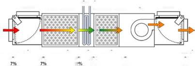
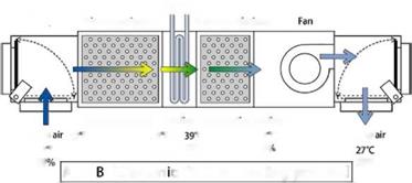 mode is switched. Each air handling unit is composed of a primary desiccant module, a cooling coil, a secondary desiccant module, a fan and two damper boxes to control air flow. The well water
COOlmg coil
![]()
Cooling coil
Fig. 1. Schematic diagram of solar desiccant cooling system.
is assumed as cooling water for cooling coils without a refrigerator. The rain water and the cooling tower can be used to cool the heated air for the cooling coil. The air flow rate of 1000 CMH is supplied by the one of the fan.
In regeneration process, the primary desiccant module (silica-gel) is regenerated by the collected hot and dry air and the collected hot and dry air become the little hot and humid air. The little hot and humid air become the humid air by the cooling coil. The second desiccant module absorbs the moisture of the humid air and the air is exhausted to outdoor.
In dehumidification cooling process, the humid fresh air is dehumidified by the primary desiccant module and is cooled by the cooling coil and the secondary desiccant module. The evaporative cooling is used by the stored moisture of the secondary desiccant module in regeneration process. The dehumidified fresh air is supplied to indoor.
Incorporating the regenerative evaporative cooler and the desiccant rotor, a prototype of the desiccant cooling system was built in the configuration shown in Fig. 2(a). As the sensible heat rotor, an appropriate commercial product was selected for the effectiveness of 80% at the process air flow rate of 20 CMM. The direct evaporative cooler at the supply air outlet was omitted in the prototype for simplicity. Since the process in the direct evaporative cooler is adiabatic, the omission of it does not influence the cooling performance. The exterior dimension of the completed prototype is 700(W) x 800(D) x 1,900 mm(H).
The prototype was tested at the ARI condition (indoor: 27oC, 50%RH, outdoor: 35oC, 40%RH) for performance evaluation. The regeneration air temperature was 59.5oC. The ventilation ratio was
0. 3, that is, the supply air comprises of 30% outdoor air and 70% recirculation air. The supply air flow rate was 14.6 CMM and the regeneration air flow rate was 14.0 CMM. The rotation period of the desiccant rotor was set at 450 s.
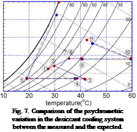
The psychrometric diagram of the desiccant cooling process is depicted in Fig. 7 from the
 0.03
0.03
![]() 0.025
0.025
0.02
0.015
0.01
0.005
measured data of the temperature and the humidity at various points in the desiccant cooling system. The circled numbers in the figure imply the numbered locations in Fig. 2(a). For comparison, the expected at the design stage from the simulation is also shown in the figure. It is seen that the actual operation of the prototype follows closely the process as was designed.
The cooling capacity and COP are evaluated with following equations:
![]()
Qcool P5V pout (i5 i1)
where Qcool is the cooling capacity, Qreg the regeneration thermal energy input, Welec the auxiliary electric input, i the enthalpy, and Vpout is the supply air flow rate.
The cooling capacity was evaluated as 4.41 kW and COP as 0.762. It should be noted that this performance was obtained with the regeneration air temperature of 59.5oC.
The electric input was assessed mostly for the fans. The pressure drop in the process air side was 430 Pa and that in the regeneration air side was 390 Pa. Based on the measured values of the flow rate and the pressure drop, the fan efficiency is estimated around 35%, which is quite low for the fan in this range of flow rate. By improving the fan efficiency, it is quite clear that the system efficiency can be improved substantially. As an ultimate case, the COP based only on the thermal energy input is found as 0.867.
It should be also noted that the cooling performance in Table 1 was obtained with the ventilation ratio of 0.3. If the cooling of the ventilation air is accounted in the evaluation of the cooling performance, that is, if i2 is used instead of i1 in Eq. (1), the cooling capacity is evaluated as 5.8 kW and COP as 1.0.
In this study, a prototype of the desiccant cooling system incorporating a regenerative evaporative cooler was designed, fabricated and tested for the performance evaluation. To this purpose, two important components, i. e., the regenerative evaporative cooler and the desiccant rotor were developed and assembled into the system.
The regenerative evaporative cooler is to cool a stream of air using the evaporative cooling effect without an increase in the humidity ratio. It is comprised basically of a pair of dry and wet channels and the evaporation water is supplied only to the wet channel. By redirecting a portion of the air flown out of the dry channel into the wet channel, the air can be cooled down to a temperature lower than its inlet wet-bulb temperature at the outlet end of the dry channels. The regenerative evaporative cooler was built by compiling the multiple pairs of dry and wet channels. The two channels were separated by a thin flat plate and metal fins were inserted into both the channels to extend the contact surfaces improving the compactness of the cooler. A desiccant rotor was fabricated using the polymeric desiccant newly developed in Korea Institute of Science and Technology (KIST). To fabricate the desiccant rotor, firstly the polymeric desiccant was prepared by ion modification of the super absorbent polymer and laminated by coating the
desiccant on a 0.1 mm thick polyethylene sheet. Then the sheet was corrugated and rolled up into a rotor.
Incorporating the regenerative evaporative cooler and the desiccant rotor, a prototype of the desiccant cooling system was built. The exterior dimension of the completed prototype is 700(W) x 800(D) x 1,900 mm(H). The prototype was tested at the ARI condition (indoor: 27oC, 50%RH, outdoor: 35oC, 40%RH) for performance evaluation. With the regeneration air temperature of 59.5oC and the ventilation ratio of 0.3, the cooling capacity was measured as 4.41 kW and COP as 0.762.
[1] W. A. Belding and M. P. F. Delmas, Novel desiccant cooling system using indirect evaporative cooler, ASHRAE Transactions 103 (1997), 841-847.
[2] S. Jain, P. L. Dhar, and S. C. Kaushik, Evaluation of solid desiccant based evaporative cooling cycles for typical hot and humid climates, Int. J. Refrigeration 18 (1995), 287-296.
[3] A. A. Jalalzadeh-Azar, W. G. Steele, and B. K. Hodge, Performance characteristics of a commercially available gas-fired desiccant system, ASHRAE Transactions 106 (2000), 95-104.
[4] I. L. Maclaine-Cross and P. J. Banks, A general theory of wet surface heat exchangers and its application to regenerative evaporative cooler, J. Heat Transfer 103 (1983), 579-585.
[5] S. T. Hsu, Z. Lavan, and W. Worek, Optimization of wet-surface heat exchangers, Energy 14 (1989), 757-770.
[6] B. S. Choi, H. Hong, and D.-Y. Lee, Optimal configuration for a compact regenerative evaporative cooler,
3rd Asian Conference on Refrigeration and Air-Conditioning, Gyeongju, Korea (2006).
[7] G.-E. Song and D.-Y. Lee, Development of a compact regenerative evaporative cooler, 13th IHTC,
Sydney, Australia (2006).
[8] G.-E. Song, S.-M. Yoon, and D.-Y. Lee, An experiment on modular regenerative evaporative cooler for commercial use, Int. Congress of Refrigeration, Beijing, China (2007).
[9] D.-Y. Lee and M. S. Park, Solid desiccant and desiccant rotor, Korean Journal of Air-Conditioning and Refrigeration Engineering 34 (2005), 36-45.
In addition to the solar driven cooling systems described above, other passive cooling systems were also integrated to the building, including Outside Air Pre-cooling by means of a horizontal ground heat exchanger (e. g., earth tubes) directly connected to the Air Handling Units (AHUs).
For night cooling, natural ventilation works in combination with Radiative Cooling. It was implemented here in the form of a series of radiative panels placed on the roof and connected to radiant floors in all office zones which dissipate indoor heat gains at night.
2.2. Active Cooling Systems
Finally, the HVAC system is completed by a Conventional 100kW Air-to-water Heat pump to
ensure good thermal comfort inside the building even when unconventional systems are unavailable.
The variety of systems that has been integrated will allow researchers to study many different combinations of passive and active systems and look for the best strategies in order to achieve the targeted energy savings.
As mentioned previously, this paper will focus on the control strategies for cooling systems that has been implemented in the PSA building situated in Almeria. The difficulty lies in the optimal management of both conventional and unconventional cooling systems with the aim of minimizing the overall energy consumption while ensuring good summer thermal comfort. This is a quite difficult equation to solve and for this reason a whole research project will be dedicated to improving the control strategy initially designed for the building launch and testing phase. The control strategy explained here is therefore an initial, non-optimized one.
In a previous paper [4], the energy and exergy performance of a solar assisted standard DEC system were studied. In this work some improvements are made to the results of the previous paper:
• The parasitic electric consumption for the operation of fans and pumps are accounted for.
• A new definition for the exergy input to the systems is considered, which accounts for the exergy content of the primary sources, namely the fuel used to feed heaters and power plants for the production of electric energy.
As far as the first point is concerned, the pressure losses Apa occurring in each component of the air — handling unit were determined by means of data provided by the manufacturers, as reported in Table 2; an additional pressure loss of 150 Pa was adopted to account for the air distribution system, which may be considered the same for all the systems. The pressure losses Apw inside the pipes for the distribution of hot and cold water were also appropriately assessed by taking into account the volumetric water flow rate (Vw), the pipe diameter and its length. The parasitic electric consumption for fans and pumps can then be assessed, assuming qf = 0.7 and np = 0.6 as the efficiency of fans and pumps, respectively, and by means of the following formulas:
As regards the definition of the exergy input to the systems, in this paper the exergy of the primary sources is accounted for, namely the exergy of the fuel burned to feed the heat generator for the production of hot water and the power plants for the production of electric energy. According to this approach, the primary exergy associated with a certain amount of electric power Pel and thermal power Qhg may be respectively assessed as:
|
Table 2. Pressure losses inside the air-handling units.
|
Here the ratio between the Higher Heating Value (HHV) of the fUel and its Lower Heating Value (LHV) is used because the exergy content of the fuel is related to its HHV, while the useful energy produced during the burning process is proportional to the LHV. In this analysis, natural gas was considered as the fuel used for the heat generator (HHV / LHV = 1.1), whereas oil was adopted for the power plants (HHV / LHV = 1.06). Furthermore, pel = 0.37 was adopted as the average efficiency for the production of the electric energy and its distribution to the final user, whereas ng = 0.90 was used as the efficiency of the heat generator. In Fig. 2 the comparison between conventional HVAC and standard DEC is reported; the comparison is based on three parameters, namely:
• the Specific Primary Energy Consumption (SPEC), defined as the ratio of the Primary Energy Consumption of the system to the overall thermal building load (QL + QS);
• the Specific Irreversibility Production (SPIR), defined as the ratio of the total Irreversibility Production of the system to the overall thermal building load (QL + QS);
• the exergy efficiency Z, defined as the ratio of the useful exergy output to the overall exergy input, accounted as primary exergy (see Eqn. 3).
V abs J
In Eqn. 3 we have considered that, when solar energy is used to assist the regeneration process, only a fraction (1-F) of the thermal load Qhc on the heating coil is covered by using fuel; the remaining fraction F is covered by solar energy, whose exergy content is considered proportional to the Carnot factor associated with the absorber plate temperature Tabs. The exergy flows and the irreversibility produced by each process are determined by means of the Gouy-Stodola equation, customized for the analysis of HVAC systems and humid air streams [5, 6]; the dead state corresponds to the outdoor conditions.
|
|
|
Solar fraction Solar fraction Solar fraction Fig. 2. Energy and exergy performance of conventional HVAC and standard DEC systems. |
The standard DEC cycle has been studied for different regeneration temperatures. Thanks to the results shown in Fig. 2, it is possible to define the minimum solar fraction F needed to attain a second law efficiency of the DEC system better than that of a conventional HVAC system. This minimum value depends on the regeneration temperature required by the desiccant wheel; as an example, when working with a regeneration temperature as high as 90°C, at least F = 0.35 is required to get a higher exergy efficiency than the conventional HVAC, whereas F = 0.15 is sufficient if the regeneration temperature is as high as 70°C. When using high regeneration temperatures, a higher thermal power is required by the heating coil, but the dehumidification potential of the desiccant wheel also gets higher, thus allowing a reduction of the size of the precooling coil (EB, see Fig. 1). For this reason, if a very high solar fraction is adopted — more or less higher than 80% — it seems to be more performing to work with higher regeneration temperatures. Further aspects will be addressed later in the paper.
When looking at the first law performance, the advantage of using solar assisted DEC system is more evident, and the energy break-even point is reached for a very low solar fraction. It has also to be underlined that the contribution of the parasitic consumption is not negligible. The exergy provided to feed fans and pumps ranges from 13% of the overall exergy input in a standard DEC system to 21% in a solar-assisted system with F = 1. In the conventional HVAC system this contribution reduces to the 5%, due to the low number of components inside the AHU.
1.1. Presentation of the installation
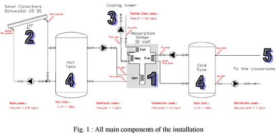 |
The aim of our solar cooling installation is to cool four classrooms (total area = 170 m2). We can notice that there are not backup systems and the average temperature in the classrooms is not steady depending of the outside conditions (Tout — Tin = 5 to 7 °C). We can see all main components on fig. 1:
1. an absorption chiller (frigorific power = 30 kW),
2. 36 solar collectors (total area = 90m2),
3. a cooling tower (cooling power = 80 kW),
4. a hot tank (V = 1500 L) and a cold tank (V = 1000 L),
5. 13 cold fans which provide frigorific power to the classrooms.
A user-defined type was developed to describe the behaviour of an ice-making ice-encapsulated cold storage. The storage can be represented like a stack of layers (nodes), each one containing a certain number of capsules. The number of capsules in each layer is directly calculated as follows:
N = Vtank і1′ Z)
capsules
y capsule 1 v layers і
where Vtank is the tank volume, Vcapsule is the capsule volume and є is the void fraction around the capsule, typically in the range 0.4 to 0.5 depending on the capsule shape. Heat balance equations over each layer yields the following:
^refVrefCpref j. ■ refCpref Tj-1 Tj NcapsulesQref^capsule
dt when mref is downward (3)
^refVrefCpref dt m refCPref Tj+1 Tj NcapsulesQref ^capsule
dt when mref is upward (4)
 |
 |
||
where Sref, Vref and Cpref are the refrigerant density, volume and specific heat respectively, mref is the refrigerant mass flow rate, Tj is the refrigerant temperature within the j layer and Qref^capsule is the heat transferred from refrigerant to capsule. The expression for Qref^capsule depends on the particular state of the PCM inside the capsule. Four conditions are possible: 1) PCM liquid, 2) PCM in transition from liquid to solid, 3) PCM in transition from solid to liquid and 4) PCM solid. When the PCM is completely liquid or solid, the lumped capacity model is used, assuming the PCM temperature is uniform in the capsule and equal to the temperature of the layer. During PCM phase transition inside the capsule, the following experimental equations, as described in [6], have been used:
where L is the latent heat of water, Vcapsule is the capsule volume, Ro is the capsule radius, 5wat and kwat are the density and thermal conductivity of water, 5ice and kice are the density and thermal conductivity of ice, Tpc is the phase change temperature, t is the time since phase change has started, and t* is the dimensionless time. For a detailed description see [8].
In a parametric study, the influences of the collector field area, size of the latent heat storage (commercially available nodule ice storage), the chilled mass flow that is to be cooled and the possible effect of dust on the reflector area, were investigated. Some results are presented below.
5.1 Evaluated Parameters
To rate the system two performance figures where evaluated: The extracted heat per incident beam radiation as total efficiency (ntotal) and the ratio between the cooling work carried out by the solar cooling system and the total cooling work required by the given process for the specified flow rate of the return flow as described in 5.3 (Solar fraction, SF).
![]()
![]() extracted, solar
extracted, solar
![]() — |y°l
— |y°l
beam, incident
Qextracted, solar
Qtotal [%]
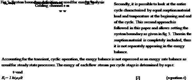 |
Exergy analysis is either applied for the identification of system irreversibilities via the calculation of exergy losses and exergy destruction, or for the assessment of system performance by calculating the exergy efficiency. As the system under consideration here is characterized by cyclic operation (fig 1) two approaches to exergy analysis are imaginable. Firstly, each cycle stage could be subject to an exergy analysis which would require taking into account the exergy of the sorption material and the adsorbate.
with Ew=E3=E4=0 during the desorption stage and Ei=E2=0 during the pre-cooling stage due to zero mass flow rate. The overall exergy balance for the cycle can then be expressed by equation 7.
£(( + E3 + E. ) — + E4 ) = Ed [J] (equation 7)
The average exergy destruction rate of one heat exchanger can be obtained dividing by the cycle time. The exergy efficiency can be expressed as the relation of exergetic product to the exergetic input. Identifying the increase in exergy between fresh air inlet and supply air outlet during adsorption as the system exergetic product, the exergy efficiency is given by equation 8.
U. Jakob1* and S. Saulich1
1 SolarNext AG, Nordstrasse 10, 83253 Rimsting, Germany
* Corresponding Author, ali. iakob@solarenxt. de
Abstract
This paper presents the development and investigation of solar cooling systems based on small-scale sorption heat pumps and chillers, respectively. An ammonia/water absorption chiller with a cooling capacity of 12 kW, the chillii® PSC12, a 17.5 kW water/lithium bromide absorber, the chillii® WFC18 and two water/silica-gel adsorption chillers with cooling capacities of 7.5 and 15 kW, the chillii® STC8 and chillii® STC15, all single effect, are specified as core components of solar cooling systems. Up to now over twenty chillii® Cooling and Solar Cooling Systems respectively are in installed in Germany, Austria, Spain, Italy, Malta, Romania, Syria, Canada, China and Australia. Different kind of applications are realised like for residential buildings, retirement home, office buildings, bank, bakery, greenhouse and institutes. The first experiences and experimental results of the installed solar cooling systems showed that the chillers and the solar cooling system work very well. Keywords: Solar cooling, absorption, adsorption, heat pump, chiller
Active air-conditioning of buildings is also necessary at European climate conditions, especially in Southern Europe. Therefore the energy consumption for cold and air-conditioning is rising rapidly. Usual electrically driven compressor chillers (split-units) have maximal energy consumptions in peak-load period during the summer. In the last few years even in Europe this regularly leads to overloaded electricity grids. The refrigerants that are currently used in the split-units do not have an ozone depletion potential (ODP) anymore, but they have a considerable global warming potential (GWP), because of leakages of the chiller in the area of 5 to 15 % per year. However, solar cooling systems provide a sustainable active air-conditioning possibility. The sorption heat pumps or chillers use environmentally friendly refrigerants and have only very low electricity demand. Therefore the operating costs of these chillers are very low and the CO2 balance compared to split-units is considerably better. The main advantage of solar cooling is the coincidence of solar irradiation and cooling demand. Particularly the sale figures of split-units with a cooling capacity range up to 5 kW are rising rapidly. In Europe the number of sold units has risen about 53% from
5.3 million in 2004 to predicted 8.1 million in 2007 [1]. The Japan Refrigeration and Air Conditioning Industry Association (JRAIA) has expected a worldwide sales of 74.4 million units in 2007. The market potential for solar cooling systems with small-scale capacity is very large, so that different companies are developing solar cooling systems/kits for the product business [2]. In case active cooling being necessary, the long running times of the chillers are the key for economic efficiency of solar cooling systems. For residential buildings in Central Europe only about 50 to 200 cooling hours occur, whereas in the southern Mediterranean area as well as for some industrial
and office buildings approximately 1,000 full load hours are necessary. An all-season use of renewable energy sources for hot water, space heating and solar cooling is here indispensable.
The project faces difficulties related to the filter supply. The university procurement is still looking to find a reliable and reasonable channel for importing the needed filters. Due to the continental climate, Yerevan is a rather dusty city: the summer very intense winds remove and bring the desiccated upper layer of the soil. While there is a huge increase in the construction rate in Armenia, the construction infrastructure yet to solve a number of problems, that includes also HVAC components supply chain.
Due to this problem the system has been stopped last autumn, to be restarted very soon.
4. Powering the DESODEC system by PV.
It has been decided to amend the DESODEC project solar installation by a 5 kW PV system. The goal of this project was to provide independent and clean electric power for DESODEC system operation.
The average electric consumption of the DESODEC system is equal to 5 kW, with maximum value reaching up to 10 kW. The PV system has an inverter of 10 kW to meet the maximal power consumption need. The system has the following components: PV field; charge controllers; grid switch; battery bank; inverter; support structure; monitoring equipment. The battery bank is a series connection of 8 units of 6 volt Rolls deep cycle led acid solar batteries. The total capacity is 1150AH at 20 amperes discharge current, and 850AH for 100 amperes discharge current. At 48 volts this constitutes about 50 kWh of power stored, with average consumption of the DESODEC system equal to 5 kW it provides about 10 hours of uninterrupted operation. When batteries are exhausted and there is no sun, the DESODEC system switches to the grid [5].
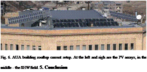
One of the interesting outcomes of this part of the project is related to the architectural solution for installing SWH and PV panels onto a complex rooftop of an existing university building, illustrated in the fig. 6.
The DESODEC system operating experience can be used to improve future setups. A number of other
projects are expected to perform as a continuation for DESODEC (see e. g. [6]).
[1] J. Farinha Mendes, A. Hambarian, H-M Henning, V. Afyan, A. Pinov — “Solar Driven Desiccant Cooling Demonstration System” — Int. Congress on “Business and Investment for Renewable Energy in Russia”, May 31-June 04, 1999, Moscow.
[2] J. Farinha Mendes, A. Hambarian, H-M Henning, Tim Selke, V. Afyan, A. Pinov, F. Luginsland — “Solar Driven Desiccant Cooling System for American University of Armenia” — Int. Workshop on “Results of Fundamental Research for Investment, May 28-30, 2001, St. Petersburg.
[3] J. Farinha Mendes, A. Hambarian, H-M Henning, Tim Selke, V. Afyan, A. Pinov, F. Luginsland — “Experience of International Cooperation on Development of Cooling Systems for Buildings Using Solar Energy” — International. Workshop on Renewable Energy Applications, June 5-8, 2001, Moscow.
[4] J. Farinha Mendes, A. Hambarian, H-M Henning, Tim Selke, V. Afyan, A. Pinov, F. Luginsland — “Sistema de Demonstragao com Energia Solar e Tecnologia DEC para Arrefecimento Ambiente Instalado na Universidade Americana da Armenia” — Accepted for oral presentation at the XI Iberian and VI IberoAmerican Solar Energy Congress to be held in Vilamoura (Algarve, Portugal), 29 Sept — 02 Oct 2002.
[5] Zhozef Panosyan, Artak Hambaryan, Kenell Touryan, Armen Tumanyan, Yeremia Yengibaryan, Mikayel Piradyan, Arsen Darbasyan, Wilhelm Akunyan. Design, “Construction and Monitoring of a Solar
Photovoltaic Station of AUA” — 21st European Photovoltaic Solar Energy Conference, 4-8 September 2006, Dresden, Germany.
[6] Artak Hambarian. “Renewable Energy Related Projects of the Engineering Research Center of the American University of Armenia. Invited conference paper”. ArmTech 2007 Congress, July 4-7, San Francisco, CA USA.