Как выбрать гостиницу для кошек
14 декабря, 2021
During the conceptual and preliminary design phases it was proven that polymeric materials offered good structural advantages and various designs using polymeric materials were considered and evaluated.
 |
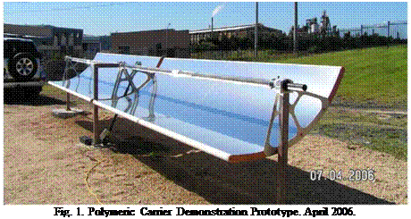
In the initial prototype (which was developed purely as a demonstrator) the structure providing and supporting the parabolic shape was intended to take the entire load on the collector. Refer to Figure 1.
During the detailed development phase it was proven that a large volume of polymeric foam material with a layer of structural skin could provide the structural integrity required. Various polymeric foam materials and structural skin materials were investigated for this purpose. Many previous attempts in manufacturing concentrating collectors using polymeric materials have failed due to the lack of long term form stability of many polymeric core materials. Form stable polymeric core materials do exist but are very expensive in volume. The concept was abandoned due to the high cost.
With a focus on reduced overall cost, a final configuration was devised whereby each component in the system had a specific objective, and the optimum geometry for each component was chosen. This lead to the choice of a single torque tube with sufficient stiffness to carry the torsional loads of the system, and a simple sandwich panel rigidly mounted to the torque tube which would provide sufficient bending stiffness to maintain the parabolic mirror surface. Mounting arms for the receiver tube were to be mounted directly on the torque tube, and the torque tube itself would also function as the rotation shaft of the system. The possibility of counter balancing the system was
also analysed and found to be cost effective as it reduced the torsional load on the system which improved the system optical performance.
This resulting system has a relatively low surface area to be laid up, has sufficiently thin core material that pre-forming the core would be reduced or eliminated, and can be packed efficiently for shipping. Furthermore, the system is readily scalable, can be produced in modules, and can utilise standard off the shelf components for mountings, shafts, bearings. On site assembly of components, and reduced component weight were also favourable, and the system also allowed for reduction of the gap between panels adjacent to the actuation cylinder.
The team developed a unique technique to form and bond the reflector (speciality aluminium mirror using physical vapour deposition (PVD) to obtain the reflectivity or speciality silvered glass mirrors) to a structural carrier in a one step manufacturing process using composite materials. The carrier consists of an efficient sandwich structure of fibre-reinforced polymeric skins and a specialised core material. Furthermore due to the excellent bond between the carrier and the mirror, the mechanical properties of the mirror are integrated into the strength and stiffness of the carrier. This process results in a lightweight, stiff and accurate surface. The use of specialised materials also provides a form stable carrier, overcoming problematic creep experienced when using low cost inferior core materials and manufacturing techniques.
 |
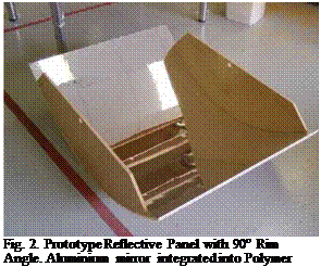
After a number of iterations with processes and materials the team successfully manufactured small prototype reflective panels with a 90° rim angle (RA) as shown in Figure 2.
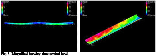
Finite element (FE) analysis of the 90° rim angle collector was undertaken which considered representative wind loads that induce bending and torque. The analysis was based on 12m/s wind speed with allowable deflection limited to 0.5° over a 10m representative trough length.
Remaining torque and bending moment loads were considered to be born by the steel torque tube/counter-weight combination as opposed to the shell and thus could be excluded.
The optimum core thickness for the composite sandwich laminate of the PTC shell was calculated to be approximately 6mm. The design called for vacuum resin infusion processing of the laminate. This was first employed on the 90° RA prototypes. Commercially available core of 10mm thickness combining a grooving pattern on its surface for vacuum resin infusion was sourced.
 |
When a subsequent decision was made to open up the rim angle to a flatter 50 degrees due to receiver re-design, the10mm core thickness choice proved useful by offsetting the reduction in stiffness caused by the reduced shell curvature and obviated the need for further FE analysis. Subsequent field trials of the manufactured prototypes confirmed this course of action. Representative FE plots of the 90 degree RA geometry are illustrated in Figures 3 and 4, firstly for magnified bending and then for magnified torque (twisting).
Fig. 4. Magnified twist due to wind load.
Several subtle but significant composite laminate modifications were evaluated in the numerical modeling and on the physical 90° RA prototypes before settling on the chosen lamination sequence. The laminate schedule features the aluminium mirror surface on the mould side which is also considered structurally effective, combined with a composite sandwich laminate.
 |
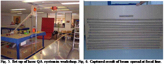
After the completion of the first of these full size reflective panels the team developed a laser measuring QA procedure to record the focal accuracy. The set-up of the laser is shown in Figure 5 and the results in Figure 6. This yielded pleasing results and generated the confidence to proceed with the remaining 7 prototype reflective panels.
To complete the design of the collector full 3D modelling and documentation of not only the parabolic reflector but also the associated steel componentry comprising the torque tube, bearings, drive system, receiver mountings, mounting legs and counter-weights etc. was conducted. This design step involved several iterations to reduce cost. The solar tracking system was developed in house and consists of a stepper motor driving through a reduction system and an extremely accurate inclinometer mounted directly on the collector. The system is controlled with a
proprietary embedded microcontroller and solar tracking algorithm. All components are sized to be economically packed into ISO shipping containers for transport and can be manually handled and easily installed on site
2.
 |
Key characteristics of the collector are
• 1.2 m Aperture by 6 m long parabolic panel elements.
• 4 panels per “standard” module — 24 m long modules.
• Torque tube is rotational axis.
• Counterweight balanced
• 50° rim angle chosen to suit a new shrouded receiver under development.
• Non-evacuated glass encased 25.4 mm stainless steel receiver with selective coating.
• 45:1 geometric concentration ratio.
• Expected maximum temp 220° C
The first test conducted on the collector was a photogrammetrical examination of the reflectors of the installed module. A surface was numerically fitted to the measured points from the photogrammetry. Using proprietary developed ray tracing software which included the Gaussian distribution of the solar disk, the CSIRO checked the accuracy of the collector. The results were very pleasing and mirrored closely the results obtained from the laser measuring QA process conducted earlier. Figure 8 shows a flux map developed from the ray trace 6 mm below the focal line of the parabolic trough. The results from the photogrammetry and laser QA confirmed the accuracy of the manufacturing process and installation.
|
1st International Congress on Heating, Cooling, and Buildings " ‘ 7th to 10th October, Lisbon — Portugal *
Fig. 8. Output from Photogrammetry test. Graphical representation of the flux density 6 mm below the focal line. |
The prototype field was integrated hydraulically (thermal oil) and for control (solar tracking) into the CSIRO Energy Centre solar facility. Each collector module was instrumented so as to measure the inlet and outlet temperatures of the thermal oil. The facility is equipped with a pyrheliometer and weather station and Direct Normal Irradiance and weather data is collected continually. The volume flow and temperatures of thermal oil are sampled and recorded at fixed interval (say 10 seconds). An electro-thermal heating element in the thermal system allows for the thermal oil to be raised to preset temperatures prior to the commencement of testing. This set-up was used to commission the collectors and conduct preliminary tests to determine the collector thermal performance. The preliminary performance test proved that the designed, manufactured and installed prototype was meeting or exceeding expectation. The tests also reinforced the need for more accurate temperature and flow measurement and assisted in establishing a robust data acquisition and analysis system. A test procedure was developed based on the ASHRAE Standard 93-2003 Methods of Testing to Determine the Thermal Performance of Solar Collectors. To satisfy the requirements of the test standard a method was needed to control the inlet temperature of the thermal oil. A portable test rig comprising a pump, flow meter, oil cooler, temperature controller and temperature sensors has been designed. Construction of the test rig is due to commence and formal thermal efficiency tests will be conducted thereafter. Final test results will be published thereafter.