Как выбрать гостиницу для кошек
14 декабря, 2021
A detailed full dynamic simulation model of the installed system which considers the electricity consumption of all installed components (fans, pumps, etc.) has been developed by zafh. net in the simulation environment INSEL [5]. The simulation model is used to analyse the effect of different storage charge and discharge options. A very small time step of 10 seconds is used for an accurate consideration of all thermal capacities in the complex system. The complete model has been validated against measured data of the installed system. Figure 2 shows the measured performance of the solar cooling system together with the simulation results for one day in August 2007 [1]. A comparison of the simulated and measured outlet temperatures of the generator, condenser and evaporator of the ACM and of the collector field clearly visualises that the performance of the installed system is very well described by the developed simulation model.
[1] Thermo-economic optimisation shows that for solar thermal systems it is beneficial to oversize the solar
The design and method of manufacture has been protected internationally by patent applications which have been lodged in Patent Cooperation Treaty member countries.
[4] Introduction
Solid desiccant cooling has been proposed as an alternative to vapour compression refrigeration for space cooling. It is an environmentally attractive solution, which does not require ozone depleting refrigerants and can be run off low temperature waste heat or solar heat.
Utilising a solar heat source appears to offer potential for approaching zero emissions HVAC. However, some form of thermal back up, such as an electric chiller or a gas heater, is normally provided to overcome the intermittent availability of solar heat. Significant fossil fuel energy consumption and associated greenhouse gas emissions can arise from this backup thermal source.
To minimise greenhouse gas emissions, it is useful to explore the potential for operating without backup, and allowing increased fluctuations in thermal comfort conditions inside the occupied space of the building. In a previous paper, White et. al. [1] investigated the performance of a once — through solar desiccant cooling system, for airconditioning a commercial office space. The study utilised the TRNSYS computer simulation software package to explore the range of thermal comfort conditions that might be expected inside a typical office building when the solar desiccant system is operated, without a backup supply of cooling or heating, in Sydney, Australia.
Using an airflow optimised for a 60°C regeneration air temperature (4.53 airchanges per hour), the temperature inside the occupied space was found to exceed the target temperature of 26°C for 196, 131 and 87 hours per year for flat plate solar collector areas of 0.083, 0.167 and 0.333 m2 per m2 of floor area respectively. These results appear to indicate that some form of backup thermal source is likely to be required for a small number of hours per year.
The first set of experimental data for the distribution tube was analyzed by the factorial design analysis using MINITAB version 15.
Factorial design analysis is a statistical method in which every level of one factor is tested in combination with every level of another factor. In general, in a factorial analysis, all possible combinations of factor levels are tested [5].
Four variables (factors) were considered to have the highest influence on the distribution test. The first factor is the LiCl volume flow rate with three treatments (levels) with a range between 0.3 l/min-1.2 l/min. The second factor is the bore size with five levels, ranges between 0.5 mm — 0.9 mm. The third factor is the distance for each throttling-bore from the LD feed-box entrance with ten levels, ranges between 4 cm-58 cm. The forth factor is the run time for each test with two levels (10 min and 15 min). Two replicates were taken for each trial in order to get an unbiased estimation. Since the number of levels for the studied factors is not equal, general full factorial design was used to analyze the measured data. The significance level a of the test is 0.05.
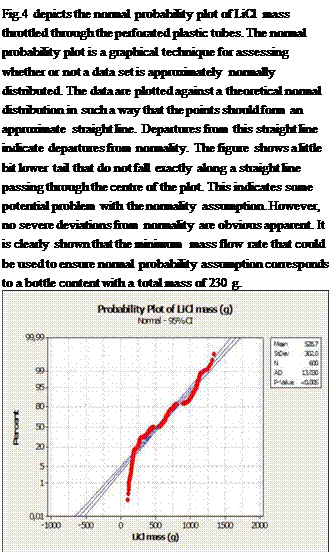 |
From the output a large F-statistic and a low p-value is seen, indicating strong evidence of a correlation between the four factors and the LiCl throttled through each discharge-point. It is also shown that p-values for all terms in the test are less than the significance level. This confirms the quality of the test.
Fig. 4. Normal probability plot of the response (LiCl mass)
Fig. 5. Residual versus the response (LiCl mass)
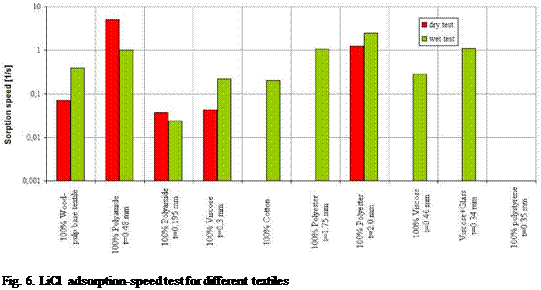 |
The second set of tests focused on the absorption capacity and diffusivity of different textiles. A probe of lithium chloride solution (45% salt concentration by weight) was poured on a taut piece of textile. Then the needed time for the LiCl droplets to be completely adsorbed by the textile fibers were measured. The tests were carried out for the textiles in dry and wet state. Fig. 6 shows the adsorption speed for probes of one of the promising wood-pulp based textiles, polyamide, viscose, cotton, polyester and polystyrene fibers.
The best results were obtained for pure wood-pulp, polyamide and polyester fibres. Different probes of polyester and polyamide fibres reveal essentially inferior adsorption speed. Therefore the material itself is not the only factor influencing the adsorption speed. During the tests a strong dependency was detected between the sorption speed and the material thickness, the pore size and the weaving structure. Further tests must be carried out to clarify these influences. A good LiCl diffusion behaviour through the pure wood-pulp fiber was proved in the experiments.
This paper presents experimental tests and a factorial design analysis of a desiccant distributor system which will be used in the prototype of a LD regenerator. It shows the optimal conditions that will ensure even distribution and the applicability to serve a wide range of desiccant flow rates. Furthermore, it presents experimental investigations for different textiles in order to choose the best textile with the highest adsorption speed and the finest desiccant diffusion through the textile fibers.
The factorial design analysis shows the optimal diameter of the throttling-holes, and the optimal spacing between those throttling diameters. Those optimal values will ensure a fairly even distribution and it will serve a wide range of desiccant volume flow rates, which will make the LD distributor flexible to serve the requested volume flow rate requested by the air conditioning cooling load.
The experimental investigations related to textiles approved that new textiles such as pure wood — pulp fibers and polyamide perform much better than traditional textiles currently in use such as cotton.
Further investigations must be carried out to clarify the influence of the textile thickness, the pore size, the desiccant type and the weaving structure on the adsorption behaviour of textiles. Experimental investigations might be considered concerning: the durability of the throttling-bores against the desiccants corrosivity, the influence of the regenerator operating conditions (high temperatures and corrosivity) on the textile performance, the effect of using higher desiccant concentration e. g. 40% on the distribution through the perforated tubes (in case if the LD distributor will be used in a conditioner instead of a regenerator), the necessity to flush the distributor and the solution that might be used.
[1] Kathabar technical information, www. kathabar. com.
[2] Krause M., Saman W., Vajen K. (2005), Regenerator Design for open Cycle Liquid Desiccant Systems — The-oretical and Experimental In-vestigations, Proc. Interna-tional Conference Solar Air-Conditioning, Staffelstein, 6. — 7.10.2005.
[3] Lowenstein A., Slayzak S., Kozubal E. (2006), A Zero Carryover Liquid Desiccant Air Conditioner for Solar Applications, ASME/Solar06, Denver, USA.
[4] Lavemann E., Peltzer M. (2005), Solar Air Condition-ing of an Office Building in Singapore using Open Cycle Liquid Desiccant Techno-logy, Proceeding of the International Conference on Solar Air Condi-tioning, Staffelstein, 06.-07.10.2005
[5] Montgomery, D., Runger G. (1999), Applied statistics and probability for engineers, second edition, John Wiley and Sons, Inc. New York.
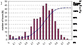
Fig. 10 shows the statistics of the driving temperatures. It can be seen, that in the heating mode driving temperatures below 68°C were also used. Unlike in the cooling mode, where the temperature in the buffer storage is used in order to decide whether high enough temperatures are available for operation, in the heating mode the machine is switched on whenever heating is required, assuming that the temperature in the heating net is always high enough. From the resulting operation conditions it can be seen that the available temperatures in the heating net present a high variation and are not constant at 72°C as the design values may suggest.
The temperatures fed into the heating coil (Fig. 11) were moderate (24°C to 30°C) and those from the boreholes where quite high (13-15°C). In Fig. 12 the temperature lift is shown. As in the cooling mode, only low temperature lifts were required, with a mean at about 13K. The power extracted from the borehole system was between 2.5 and 3.7kW (Fig. 13).
Fig. 10. Frequency diagram of driving temperatures. Fig. 11. Frequency diagram of temperatures to the
![image635 Подпись: temperature lift: T_MT_out-T_NT_in [K] Fig. 12. Temperature lifts in the heating mode Operation in the heating mode](/img/1154/image635.gif) |
 |
heating coil (output temperature from the heat pump)
In Erro! A origem da referenda nao foi encontrada. the operation temperatures on November 15th, 2007 as a function of time are shown. A strong variation of the driving temperature (T_HT_in) is observed. This variation is inherent to the operation of the heating net and out of the control of the present system. Nevertheless it shows that even though the heating net is designed for a constant temperature of 72°C reality shows also much lower temperatures. Again, the periodic temperature peaks characteristic of adsorption systems can be seen clearly in all return temperatures (T_HT_out, T_MT_out, T_NT_out).
|
|
|
О Ф =3 2 ф CL E ф |
|
80 70 60 50 40 30 20 10 |
|
06 |
|
08 10 12 14 16 18 20 22 |
|
time of the day |
Fig 14. Temperatures in the heating mode for the 15th of November, 2007.
As a conclusion it can be said that the installed adsorption chiller worked reliably and the rated COP and chilling powers were within the expected range. Certainly the operation conditions were very favourable as the required temperature lifts were around 10K in the cooling as well as in the heating mode. These low temperature lifts favour a high performance of the machine.
The application required cooling only during the day, thus the control switched the machine on only in this period. With this background, the solar fraction for cooling was around 60%. This may be different and may result in a different system design (e. g. larger solar field or larger storage) if cooling is also required beyond the hours with solar radiation. The overall thermal COP of the chiller for cooling operation was 0.574. In this period 1230kWh of cooling was produced with an electricity requirement to operate the system including cold distribution of 125.8kWh.
In the heating operation the overall thermal COP was 1.43, with a total of 3274kWh of useful heat produced and an electricity requirement of 180.5kWh. As it is difficult to obtain high temperatures from the solar collectors in the winter season, only 5% of the driving heat was provided from this source.
The electric power requirement of the system, excluding the pump in the solar loop, is about 500W, independently of the operation mode, cooling or heating power. This power requirement includes cold and heat distribution, therefore any comparison has to be done taking into account the whole system as a basis. However, using the boreholes as heat rejection system favours the low electricity consumption as no additional cooling tower was required for the cooling mode.
The temperature diagrams show strong fluctuations in the driving temperatures, especially when operated in combination with the heating net. The fluctuations were less when heat from the solar system was used. This shows the attenuating effect of the solar buffer storage. Strong fluctuations in the return lines from the machine are inherent of the periodic operation of adsorption units and have to be taken into account in the design and evaluation of the system. As a conclusion, it has to be analysed if some kind of small mixing storage or any other thermal capacity device to attenuate the temperature peaks is required in order to operate such an adsorption system in a stable way.
The reliable operation of the installed unit opened up the path to an improved pilot product, called ACS08, produced and offered by the company SorTech [3].
[1] T. NMez, M. Hau, H-M. Henning, »A Small Capacity Adsorption System in a Heating and Cooling Application: The German Field-test in the MODESTORE Projects, Proceedings of the 1st International Conference Solar Air-Conditioning, Bad Staffelstein, Germany, (2005), pp. 335-340.
[2] T. NMez, W. Mittelbach, H-M. Henning, »Development of a Small Capacity Adsorption System for Heating and Cooling Applications^, in: International Journal of HVAC&R Research, USA, (2006) Vol. 12, no. 3b, pp. 749-765.
[3] SorTech Adsorption Chiller ACS 08; www. sortech. de
In table 1 the selected building applications and energy efficiency standards are described.
[7] Coefficient of Performance (COP) = cooling or heating output (kW) divided by
electrical input. The only electrical input is 4 small circulation pumps and internal controls. COP in conventional compressor-based chillers and packaged air conditioning units is usually stated as cooling capacity (kW) divided by compressor electrical input. Since the Millennium MSS air conditioning doesn’t have a refrigeration compressor, COP is stated here as annual cooling/heating energy delivered divided by total electrical input of the pumps and internal controls.
Fig 1. Millennium MSS Air Conditioning system heating and cooling device The example below shows one of the two barrels discharging cooling.
[8] chillii® Solar Cooling System
The analysed solar driven chillii® Solar Cooling System of the Solar Next AG has been set up and installed as a test facility to cool their office building in Rimsting. This system includes a market available 15 kW LiBr absorption chiller (ACM), two 1 m3 hot water storage tanks, one 1 m3 cold storage tank, 37 m2 CS-100F flat plate collectors and 34 m2 TH SLU1500/16 solar vacuum tube collectors all facing south with an inclination of 30°, a 35 kW EWK wet recooling tower (Figure 1). For the distribution of the cooling energy chilled ceilings and fan coils are used with 16°C supply and 18°C return temperature and an automated supply temperature increase for dew point protection. An auxiliary heater is integrated in the system, but not considered in the present analyses.
[10] Introduction
The use of renewable energy in buildings is a very important challenge in order to decrease their primary energy consumption. In South of Europe, most of buildings, especially tertiary ones, need active cooling in summer; thus the set up of the solar cooling technology can often represents an important way to save fossil energy. Solar cooling technologies already exists and have shown their effectiveness at the demonstration stage. Nevertheless, a certain number of technical and economical barriers actually exist and prevent a larger set up of the systems.
[11] From the two groups in Fig. 2 the reverse result is obtained. But this is an effect of the scatter (e. g. the AAtmin value is lower than zero for AtACE=29K, which is physically not possible). The ‘real’ characteristic equation (derived from ideal data without any scatter) should be steeper, leading to positive values of AAtmin and an increased slope.
[12] Conventional AHU, whose layout and thermal cycle are shown in [1].
• Standard open-cycle desiccant system (DEC), according to the layout shown in Figure 1.
• Standard DEC provided with a desuperheater.
• Standard DEC modified with the use of an enthalpy recovery wheel, which operates a pre-dehumidification of the process air by releasing a certain fraction of its vapour content to the exhaust air.
For all the thermal cycles related to the DEC systems, the use of solar energy to assist regeneration will also be investigated (solar assisted DEC): the AHU is the same as in the previous points, but a solar section with a back-up heater is adopted to produce hot water for regeneration purposes. In order to test the sensitivity of the results to the size of the solar section, different values of the collector surface will be considered, corresponding to an annual solar fraction F ranging from 0 to 1. In order to compare the energy and exergy performance of the systems, we have considered a case study represented by the ventilation and the air-conditioning of an enclosed space with a latent
[13] Governing principles and parameters
So as to establish appropriate dimensioning guidelines, we will start by characterizing the governing principles and their link to amplitude-dampening along the pipes. We therefore will base on the simplified and analytically resolved case of a constant airflow subject to sinusoidal temperature input, with explicit treatment of diffusive heat storage into the soil [2], which yields following main insights:
• As long as the soil layer around each pipe is at least that thick, heat charge and discharge
around the pipes naturally extends over a penetration depth 8 which depends on the oscillation period:
[14] Koller, Zetzsche, Brendel, Muller-Steinhagen: Design and Operation of a small Ice Storage, 2nd International Conference Solar Air-Conditioning, Oct. 18th/19th 2007, Ostbayerisches Technologie- Transfer-Institut e. V., Regensburg, Germany, p. 359-364
[16] y is the response of the phenomena • xi is a factor or parameter influencing the phenomena • a0 is a constant effect,
• ai is the effect of single parameter
• aij is the effect of double interaction,
• aijk is the effect of triple interaction
It is evident that the number of effect to be determined will need the same number of experiments. In order to estimate the effects, each parameter varies between an upper and lower limit, so each parameter has two levels [2]. In our case we have 4 parameters; each one varying between 2 limits which mean we have 24 effects to be determined and 16 combinations (experiments) are then needed.
The following range of the parameters was considered:
• Outside temperature T1: [25, 35] [°C]
• Outside humidity ratio w1: [11, 14.5] [g/kg]
• Regeneration temperature T8 [55, 75] [°C]
• Regeneration humidity ratio w8 [10; 15] [g/kg]
Outside temperature and humidity ranges correspond to the most of the European climates (except some humid Mediterranean climates) and match with the domain of application of desiccant cooling (e. g. moderately hot and moderately humid climates). The upper limit of regeneration temperature domain is consistent with solar application with temperature not exceeding 75°C while
Dr. Tomas Nunez*; Bjorn Nienborg; York Tiedtke
Fraunhofer-Institut for Solar Energy Systems ISE, Heidenhofstrafte 2, 79106 Freiburg, Germany
* Corresponding Author, tomas. nunez@ise. fraunhofer. de
The performance of a solar driven adsorption cooling system is presented in this paper. The system consists of a reversible 5.5kW adsorption machine from the German company SorTech, a 20m2 flat plate collector field with a 2m3 buffer storage and a borehole array of three 80m boreholes. In the summer period, the adsorption machine is operated as a chiller driven by solar energy while the boreholes are used for heat rejection. In winter it is operated as a heat pump driven by the heat from a heating network and using the boreholes as low temperature heat source. The operation results presented here correspond to the period from June 4th to December 1st, 2007. The machine as well as the whole system operated reliably and as expected during the whole monitoring period. An overall thermal COP of 0.57 and an hourly mean chilling power of around 4.4kW were obtained during the cooling season. The electricity consumption was about 10% of the produced cold. During the heating season a thermal COP of 1.43 and hourly mean heating powers of 9.4kW were obtained. Frequency distributions of the registered driving, heat rejection and chilled water temperatures give a picture of operation conditions in a real application.
Keywords: adsorption, solar cooling, ground source heat exchanger, system performance
In the frame of the finished EU project MODESTORE a solar driven cooling system with a 5.5kW reversible adsorption chiller was installed at the Fraunhofer Institute for Solar Energy Systems. In a previous publication [1] first simulation results which resulted in the present design and dimensioning of the system were published. In this publication the system performance and operation results from the first operation period in both modes (cooling and heating) is presented.
G. Gutierrez*, P. Rodriguez, A. Lecuona, M. Venegas, J. Nogueira
Universidad Carlos III de Madrid (UC3M). Departamento de Ingenieria Termica y de Fluidos. Avda.
Universidad 30, 28911 Leganes, Madrid, Spain
* Corresponding Author, glgutier@ing. uc3m. es
Abstract
An experimental facility applying the concept of adiabatic absorption has been designed and built in Universidad Carlos III de Madrid. Plate heat exchangers are incorporated in the design functioning as generator, condenser, sub-cooler and solution heat exchanger. Other components include a separator and two fin-coiled tubes as evaporators. Trials were carried out in order to characterize components and performance. The range of controlled hot fluid temperature corresponds to a solar thermal energy source (below 100°C). Performance parameters, cooling capacity and COP, are expressed in terms of an ideal absorption model and compared with experimental results. The differences observed between ideal and experimental results help to identify the influence of components performances on the overall performance of the facility. The evaluation of the ideal and experimental cooling powers allows detecting a low performance of evaporators as both dry operation and overflow. Other influence factors are described and their effect is included in the thermodynamic analysis of the absorption cycle.
Keywords: Adiabatic absorption, Lithium bromide, Chillers.
|
Nomenclature |
|||
|
Nomenclature |
|||
|
COP |
coefficient of performance |
C |
specific heat capacity (kJ/kgK) |
|
h |
enthalpy (kJ/h) |
LiBr |
lithium bromide |
|
m |
mass flow rate (kg/h) |
PHE |
plate heat exchanger |
|
Q |
thermal power (kW) |
t |
temperature, external (°C) |
|
T |
temperature, internal (°C) |
wp |
pump work (kJ/h) |
|
X |
mass concentration |
||
|
Subscripts |
|||
|
ch |
chilled |
E |
evaporator, evaporation |
|
G |
generator, generation |
i |
ideal |
|
in |
inlet |
o |
outlet |
|
ref |
refrigerant |
s |
solution |
|
sep |
separator |
v |
vapour |
|
w |
water |
Greek letter:
П efficiency
Absorption machines offer the possibility of amortizing thermal solar installations during summer, at the same time avoiding polluting emissions to atmosphere and increasing sustainability.
The adiabatic process is being investigated as a method for improving absorption in a chiller. It consists on dispersing the solution inside an adiabatic chamber. The resulting heat is extracted downstream using a compact heat exchanger. Thus, the mass and heat transfer processes are split in separated apparatus. Ref. [1-3] summarizes state of the art, including experimental and theoretical studies concerning adiabatic absorption. Further works on adiabatic absorption using aqueous LiBr, focus on experimental work [4] and simulation or theoretical studies [5, 6].
Interpretation of experimental data must include the particular features, in both design and operation, of the facility here presented. For this duty, diagnostic versions of the models are of much help. A basic thermodynamic model, including such features is presented and compared with experimental results, resulting from this the detection of some operational difficulties.
The highly flexible experimental facility forms a single-effect water — lithium bromide absorption cooling system. The test facility design incorporates compact PHEs, due to the well-known benefits regarding to high heat transfer capacity in a reduced volume.
The absorption process takes place in an adiabatic chamber and the heat is extracted in an external PHE (subcooler). Because the solution absorbs less vapour as its temperature is higher, it is necessary to re-circulate part of the solution to the absorber after it has been cooled in the PHE (mr). Both the solution coming from the generator mstrong and the re-circulated solution mr flow
inside the absorber as free falling drops. The experimental setup configuration, the data acquisition system and the experimental procedure were described in detail in a previous work [7]. Fig. 1 shows a diagram of the experimental facility.
The facility is highly instrumented, such that individual component performance can de evaluated.
Data of temperature, pressure and mass flow rates in every component were recorded in intervals of 0.5 seconds in order to accurately determine steady state periods. The experimental setup was configured to allow determining COP and thermal powers exchanged in the different components.
|
Fig. 1. Diagram of the experimental facility 2.1. Experimental uncertainty analysis |
A complete calibration process is periodically carried out for all instruments showed in Fig.1. This way, measurement errors can be reduced as far as possible. The uncertainty for an experimental result R, which is function of n different parameters x, is calculated as:
|
|||
|
|
||

The uncertainty of performance parameters reached 16% at the worst case, see Fig. 4.
1.1. System and operation concept
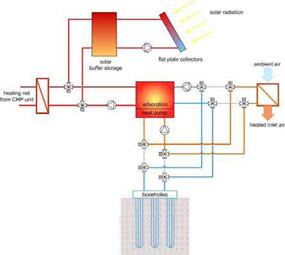
The system concept is shown in Fig. 1. The core components are the reversible adsorption machine which can be operated as a thermally driven chiller or heat pump and the borehole system that is used as heat rejection system for the chiller mode as well as the low temperature heat source for the heat pump mode.
In the summer operation mode (left schematic in Fig. 1) the adsorption machines works as a thermally driven chiller. It is driven by the heat from the solar collectors. A connection to the heating network of the building works as a heat backup in case of not sufficient solar driving heat. The system provides cooling to a cooling coil in the air handling unit, which is installed in the inlet air duct to the institutes’ canteen kitchen (3000m3/h). The waste heat from the chiller is rejected through the borehole system.
 |
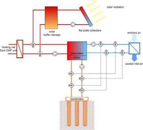 |
In the winter operation mode (right schematic in Fig. 1) the adsorption machine is working as a thermally driven heat pump. It is driven by heat from the heating network of the institute, which comes form a CHP unit, and lifts low temperature heat from the boreholes to the useful temperature level. This useful heat is used in a heating coil to pre-heat the air in the main duct of the ventilation system (9000m3/h).
Fig. 1. System schematic with summer (left) and winter operation mode (right).
The system installed at the Fraunhofer Institute consists of a solar collector array of 20m2 with a 2m3 buffer storage and three boreholes of 80m each. An adsorption chiller ACS05 from the German company SorTech AG with a rated nominal cooling power of 5.5kW is used. This chiller is a pre-series development based on a previous prototype presented in [2].
For a general application in the residential sector this system layout offers the following advantages:
• The solar system is used through the whole year. In winter it is used for solar assisted heating and in summer it provides the driving heat for the cooling system.
• The reversible adsorption machine is also used during the whole year: as a heat pump in winter and as a thermally driven chiller in the summer period.
• In the heat pumping mode the adsorption system enhances the energy output of the driving heat source through the use of ambient heat from the boreholes.
• The borehole system also serves two purposes: first as a low temperature heat source in winter and second as a heat rejection system for the chiller in summer. Thus the boreholes are not only used year round but are also regenerated in the summer season.
• In favourable conditions and periods of low cooling power requirements, the installed boreholes can be used for direct cooling.
Nevertheless, neither the direct solar heating nor the direct cooling with the boreholes has been implemented in the present system.
2.2. Control procedures
The operational concept foresees an operation only during weekdays. The operation conditions are as follows:
Cooling operation is carried out when:
• the inlet air temperature exceeds 20°C (2K hysteresis),
• the air temperature in the kitchen is above 23°C (2K hysteresis),
• the time is between 6:45 and 16:00 o’clock.
Heating operation is carried out when:
• the inlet temperature in the main air duct is below 14.5°C (3K hysteresis),
• the inlet air temperature is above 3°C (freeze protection of the machine),
• the time is between 6:45 and 19:00 o’clock.
Solar heat is used whenever the mean temperature in the upper part of the storage is above 73°C with a 5K hysteresis for turning of solar heat supply.
In spring and autumn it may happen that the air temperature falls below 14.5°C in the mornings and thus the heating mode is activated, but later during the day temperatures in the canteen kitchen rise above the threshold for cooling operation. In these cases the system is operated in the heating mode first and later in the cooling mode. This operation is called ‘alternate mode’.
The volume flows in the three circuits are kept constant and correspond to the nominal flows required by the chiller. Energy efficient pumps have been installed and the flow rate is set via the three power steps of the pumps.
3. Data acquisition and evaluation
A new prototype of the reversible adsorption machine was installed in spring of 2007 and is in operation since then. In the summer season of 2007 about 282 hours of operation in the cooling mode have been monitored. Evaluation is carried out at three levels:
1. performance of the chiller as a component
2. evaluation of the operation conditions of the whole system for system optimisation
3. evaluation of the overall systems energetic performance
These three evaluation levels address each a different group: while the first is mainly important for the chiller manufacturer in order to decide if the machine is working as expected, the second level targets the system developers which are interested in the optimisation and smooth operation of all system components in order to optimise the energy efficiency and thus produce the highest possible savings for the end-user. This result is covered with the third evaluation level.
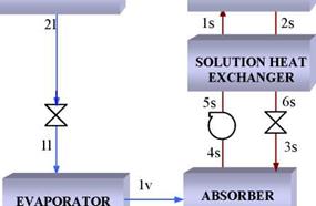
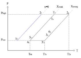
Fig. 2 represents the thermodynamic states of the ideal simple effect absorption cycle, assuming mechanical, thermal and chemical equilibrium and assuming energy degradation exclusively concentrated on expansion valves. Steady state mass and energy balance in components yield the following equations:
|
Evaporator (no superheating): |
|
|
Qm= m ref, K — h1); h1 = К |
(2) |
|
m ref, i X strong X weak Considering = |
(3) |
|
weak strong |
|
|
|
|
|
|
|
|
|
|
|
|

(a) (b)
Fig. 2. (a) LiBr/water absorption cycle. (b) Diagram P(T)-T LiBr/water
Generator (no superheating):
Mass balance:
|
Energy balance: Qoi = ™strong • h2s — mweak * К + ™^ ,г * h2v ; T2s = T2v |
![]()
™ weak = ™ strong + ™ ref, г
Solution heat exchanger:
![]() T — T T — T
T — T T — T
n = Js _4s = 2s 3s
hex, i
T1’s — T4s T2s — T 3’s

|
|
|
|
|
|
|
|
|
|
 |
|
 |
|
|
|
|
|
|
|
|
|
|
|
|
|
|
|
 |
|
|
|