Как выбрать гостиницу для кошек
14 декабря, 2021
An ice-making storage was selected as the cold thermal energy storage system. Compared to other static ice-making systems, such as the ice-on-coil type, the ice-encapsulated type offers the advantages of low cost, simplicity and wider heat exchange area. The phase change material (PCM), e. g., de-ionised water, is encapsulated in spherical capsules of relatively small diameter, usually in the range 50 to 100 mm. The capsules are packed into a conventional tank and the void
volume around the capsules is filled with refrigerant fluid, such as water glycol solution. The phase change process is described in [6]. During charging, cool refrigerant flows around the capsules and ice starts forming from the internal surface towards the centre of the capsules (see Fig. 7.). The capsules are conceived to allow for ice expansion. During discharge, refrigerant circulates around the capsules and gets chilled by the frozen capsules. The ice starts melting, again from the internal surface towards the centre of the capsules (see Fig. 8.).
During the design phase, a detailed model of the solar thermal plant has been developed in INSEL [2] and some simulations have been done in order to predict the energy produced by the solar thermal system [3]. Those simulations have been performed using meteorological data of the INSEL database. Performance analyses of the solar plant have been done with the monitored data for the period between March and June 2008 [4]. The results of the yearly simulated predictions and the measured data of 4 months of operation are shown in the table 1:
|
Table 1: Yearly simulated predictions and measured results of 4 months of operation (March-June 2008)
|
Several days with different operating conditions (solar irradiation, control strategy) have been simulated and compared with measurement data. The nomenclature used in the schema corresponds to the different sensors represented in figure 1. The measurement data used for the simulation are mean values calculated over 5 minutes time step. Those data were obtained from the monitoring system of the University of Applied Sciences Offenburg. Figures 2, 3 and 4 show the simulated and measured values for 3 different days.
|
|
|
|
|
|
|
|
|
|
|
|
|
|
|
|
|
|
|
|
|
|
|
|
|
|
|
|
|
|
|
|
|
|
|
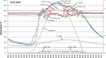
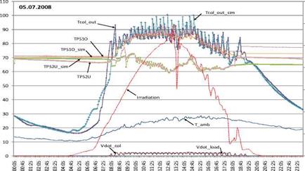
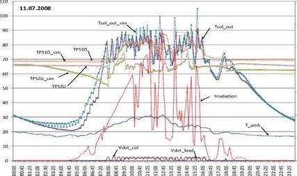
Figure 2 (10th May) represents a sunny day with constant collector volume flow. The control strategy has been recently modified in order to reduce the electricity consumption of the collector pumps, figure 3 and 4 shows the results with the new control for both sunny and cloudy days.
The total investment cost of the solar cooling system is calculated adding the cost of the solar thermal field and the cost of the sorption chiller, plus a 20% of cost installation. The first one is determined from the specific solar cost [8] and the computed surface in the previous section. The cost of the thermal chillers is much more difficult to obtain. Table 3 shows some specific costs found in the literature ([5], [6]) for the absorption chillers. Fortunately in the case of the adsorption chiller the manufacturer itself provides the economic data that could be seen in table 4.
The results obtained (tables 5 and 6) indicate that the systems with high selective Flat Plate Collectors would achieve the 700 MWh at a lower price. Among them, the systems with absorption chillers are the best option with a cost around 780.000 €. Compared to this, the more economical FPC-adsorption system is 12% more expensive. If subsidies of the Polycity project for solar collectors and adsorption chiller are taken into account, the absorption-FPC systems are still the most economical option but with the adsorption-FPC with an additional cost of less than a 5 %.
The main drawback of FPC systems is that they require more area to be installed and that also could have important economic implications that are not considered in this analysis.
In the previous study [3] the result was totally different, being the best option the combination of the adsorption MYCOM ADR-80 with FPC collectors. There are several reasons for this change. First of all the absorption chiller considered now has a higher COP which leads to lower collectors areas. Secondly, in the case we are dealing with now, the specific cost of the adsorption chillers are 15 — 30 % higher and the specific cost of the absorption chillers 25 % lower. Finally, we used another model to simulate the thermal chiller that brings more accurate results.
Then it is evident that it is necessary to be aware that the economic results are very sensitive to the specific costs of the solar collectors and thermal chillers. Then the final decision will depend of the specific values of these parameters in each particular case.
|
Absorption Chiller |
Specific chiller cost € / kW |
Total cost |
||
|
Ref [6] |
Ref [5] |
Assumed in this analysis |
€ |
|
|
Broad BDH-65 633 kWc |
300-400 |
225 |
300 |
198900 |
|
Broad BDH-50 512 kWc |
330-430 |
250 |
325 |
166400 |
|
Table 4. Specific cost and total cost of the adsorption chillers.
|
|
Table 5. Economic results for different collector technologies combined with absorption chillers.
|
|
Table 6. Economic results for different collector technologies combined with adsorption chillers.
|
The results obtained in this study suggest that the best system configuration to produce the required 700 MWh of cooling consist of a selective FPC field of 1888 m2 with a tilt angle of 35° and using the absorption chiller of 663 kWc driven at a temperature of 85 — 90°C. The total cost of solar cooling plant using an adsorption chiller is around 770.000 €, 595.000 € if potential subsidies are included. Despite this result, it is necessary to be aware that the economic results are very sensitive to the specific costs of the solar collectors and thermal chillers. Then the final decision will depend of the specific values of these parameters in each particular case.
From the point of view of energy efficiency, the absorption-ETC-CPC system is the best option, with a maximum annual performance of 606 kWh/m2y of chilled water production. The important disadvantage of this system is the high cost of the ETC-CPC collector technology.
Also it has been demonstrated that the new thermal chiller TRNSYS model (type 811), developed specifically for this analysis, could be used to simulate both absorption and adsorption chillers with enough accuracy.
The authors acknowledge the support of the European Commission under the Concerto Programme to the Polycity Project n°:TREN/05FP6EN/S07.43964/51381.
[1] POLYCITY — Energy Networks in Sustainable Cities. Sixth Framework Programme. Concerto Programme. http://www. polycity. net/en/cerdanyola-barcelona-project. html.
[2] A. Kuhn, F. Ziegler, Operational results of a 10 kW absorption chiller and adaptation of the characteristic equation, Solar Air Conditioning Conference 2005, Shaftelstein, Germany.
[3] J. Lopez-Villada, J. C. Bruno, A. Coronas, Analysis of solar thermal cooling technologies in district heating and cooling networks. Solar Air Conditioning Conference 2007, Tarragona, Spain.
[4] TRNSYS 16 Program Manual, Solar Energy Laboratory, University of Wisconsin, Madison, USA, 2004.
[5] CHOSE — Energy Savings by Combined Heat Cooling and Power Plants (CHCP) in the Hotel Sector. European Commision. Save II Programme.
[6] H. M. Henning, (2004). Solar Assisted Air-Conditioning in Buildings, Springer-Verlag, Wien
[7] MYCOM — AdSORPTON CHILLER, Construction and Data Catalogue. Albring GmbH — Industrial Agency
[8] Institut fur Solartechnik SPF. Solar Thermal Collector Catalogue 2004.
L. Bujedo1*, J. Rodriguez2, P. J. Martfcnez3, L. R. Rodriguez4 and J. Vicente1
1 CARTIF, Parque Tecnologico de Boecillo Parc 205, 47151 Boecillo, Spain
2 Institute for Renewable Energy, EURAC Research. Viale Druso 1, 39100 Bozen/Bolzano. Italy
3 Miguel Hernandez University, Av. De la Universidad s/n, 03202 Elche Spain
4 University of Burgos, E. Politecnica Superior Ed. La Milanera, C/ Villadiego, s/n,. 09001 Burgos (Spain)
* Corresponding Author, luibuj@cartif. es
Abstract
The present work has the aim to evaluate in a qualitative and quantitative way the influence, on the performance of the solar cooling installations, of two fundamental aspects: the hydraulic configuration and the implemented control. In order to do that they has been established three basic configurations and six control strategies for each one of them. The three first control actions act on the solar part and the other three on the thermal chiller, and so there are 18 simulations carried out on the simulation environment TRNSYS. Thanks to that they have been evaluated and compared the most important parameters: solar production, solar fraction, COP etc. As can be seen, the results have shown important variations on the obtained data. Different control actions applied to the solar part have repercussions on the performance of the chiller and vice versa, different control systems for the chiller, produce changes on the working conditions of the solar installation. Besides there can be seen how the most adequate control for the solar installation is the one with flow variation, combined with start up by critical radiation. The control for the chiller that better results gives is the one based on variable flow with pump. The cold storage produces a reduction of the performance of the installation, but from the point of view of design, allows having an absorption chiller of smaller size.
Keywords: solar cooling, control, hydraulic configuration, performance.
During the years 2003 to 2006, it was carried out the project “Optimization de los Procesos de Refrigeration Solar” (Solar Cooling Processes Optimization) by the Research Centre CARTIF in association with the Universities of Burgos and Miguel Hernandez from Elche. This project called ORESOL was financed by the Education and Science Ministry of Spain (with CICYT funds).
One of the main goals of this project was to analyze and evaluate the effect of the control strategies on the solar cooling installations. In order to do that, it was considered that the most suitable way was the execution of simulations with different configurations and control strategies allowing the comparison of the results and the quantitative assessment of each one of them. They were proposed three basic hydraulic configurations: direct use installation, total use installation and installation with cold storage. Six different control strategies were applied on each one of them.
In this way, apart from evaluating the level of interaction that have the actions carried out over each part of the installation, it’s evaluated the quantitative effect.
A multichannel data logger Yokogawa MX 100 has been utilised and programmed on the LabView platform to fulfil the tasks of data acquisition, monitoring and system control. Typologies, numbers and displacement of the sensors installed for the monitoring as far as the indicators used to evaluate the performances of the system have been chosen taking into account the recommendations included in the guidelines and monitoring procedures of the Task 38 “Solar Air Conditioning and Refrigeration” of IEA. The system is fully operating since March 2008. Monitoring results presented are related to the summer season operation and are referred to the month July 2008. The operation time schedule was from 7.00 to 19.00 every day of the week. Outside air conditions in the observed period were averagely moderate with a mean temperature and humidity ratio respectively of 30.1 °C and 13.9 g/kg and peak values of 34 °C and 17.4 g/kg. The maximum registered cooling load of the building was
18.1 kW. Latent loads simulated in the building were variable in the range of 2 to 3.6 kW that corresponds respectively to an equivalent number of occupants of about 30 to 60.
2.1. Validation test for both Types with laboratory data
To validate both Types the models are fed with the ILK test data at first. These data have been used to determine the performance data file for Type 307 as well as the parameters of the characteristic equations for Type 177. In Fig. 3 and Fig. 4 the simulated cooling capacities (QEsim) of Type 307 with PD1 and PD2 are plotted relative to the measured test data (QEILK).
Comparing both plots an apparently lower agreement of the simulation results can be observed when using the performance data PD2. Nevertheless PD2 is more realistic since with PD1 also the measurement scatter is interpolated instead of a continuously increasing cooling capacity. It is seen from Fig. 1 that e. g. the value at 85°C is fitted much better when a stepwise linear interpolation between neighbouring points is performed with PD1 instead of a global interpolation over the full range 80<tGi<95°C as it is done with PD2. Since there is no physical reason for a steeper increase of Qe between 80°C and 85°C and a more modest increase between 85°C and 90° PD2 is the better model — physically, not numerically. As explained earlier, with PD2 also a quasiextrapolation is possible, since indirectly a kind of characteristic equation method has been applied by the global interpolation procedure when preparing PD2.
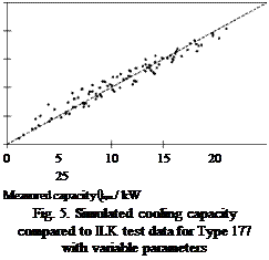
![]() Comparing the test data to those of Type 177 (cf. Fig. 5) significant higher deviations can be observed as in Fig. 5. The reason is that the PD2-method, allows the global slope of e. g. Qe = f(tGi=var, tACi=const) to increase and decrease again, although tACi is continuously increasing or decreasing. Here the variation of slopes is more limited due to the combination of all three external temperatures in one value (AAt*). Although physically reasonable this reduces the possibility of numerical fitting.
Comparing the test data to those of Type 177 (cf. Fig. 5) significant higher deviations can be observed as in Fig. 5. The reason is that the PD2-method, allows the global slope of e. g. Qe = f(tGi=var, tACi=const) to increase and decrease again, although tACi is continuously increasing or decreasing. Here the variation of slopes is more limited due to the combination of all three external temperatures in one value (AAt*). Although physically reasonable this reduces the possibility of numerical fitting.
This Task takes a look at the components of the machines, the internal parts as e. g. the exchangers, ejectors, covering materials, or chemical components as the working pairs or the absorptive materials.
Similarly to Task B, previously to the comparison, a methodology of properties characterisation must be described to create with them a database with the available and upcoming materials, their stability and their known problems and incompatibilities.
Although the main focus lies on the internal elements, also the external ones are going to be studied as can be the heat rejection systems and all the auxiliary components existing in a facility.
1.2. Technologies
The following cooling technologies are feasible to be combined with solar thermal collectors in order to save energy:
• Evaporative cooling: by pre-treating the inlet air stream to improve its thermodynamic conditions
• Absorption: by providing thermal energy to the generator to separate the refrigerant from the absorbent
• Adsorption: similar to the absorption process, external heat helps to separate the refrigerant from the adsorbent
Evaporative cooling systems have high values of COP, which are optimal if the entering air has a temperature higher than 35°C with a relative humidity lower than 20%. Changes in these conditions entail a quick decrease of COP. Unfortunately, these optimum conditions are not registered in a zone of Spain wide enough to generalize them, being the reason of not having considered this technology as an alternative in the analysis.
Absorption process is based on the quality of some liquid substances of being able to absorb particles of other fluids into its molecular structure under certain conditions of pressure and temperature. These substances are classified in pairs corresponding to their affinity to absorb/being absorbed, being most common pairs water — lithium bromide and ammonia — water, absorbed and absorbent respectively.
The thermodynamic cycle is similar to a traditional vapour compression cycle. It has four main elements: absorber, generator, condenser and evaporator; and has four stages: the refrigerant (absorbed) enters into the absorber and it is circulated by an electric pump into a transport solution (absorbent) to the generator at a high pressure. Inside the generator, the solution receives heat from a thermal energy source, causing a desorption of the refrigerant from the transport solution. The high pressured refrigerant is conducted to the condenser as saturated vapour, while the transport solution goes back to the absorber through a pressure reducer valve. The refrigerant changes its state from vapour to liquid in the condenser, passing through an expansion valve to the evaporator as low — pressured liquid. Within the evaporator, the refrigerant is converted into vapour again by extracting heat from a secondary flow stream, obtaining the final cooling effect.
The highest energy demand takes place in the generator, where heat is needed to run the desorption process. The key of this technology is that the thermal energy can be freely supplied by a thermal solar field, resulting in an energy cost saving of almost 100%.
Adsorption process is similar to the absorption one, with the exception that the adsorption process uses a solid instead of a fluid to adsorb the refrigerant. As occurs in the absorption technology, the main energy consumption comes from a thermal energy source (i. e. solar collector field), using electric energy only for the recirculation pumps.
T. Soutsos et al. [1], in a comparative analysis between adsorption and absorption systems in Greece (similar latitude than southern Spain), showed that the economic results of absorption are clearly more favourable than those corresponding to adsorption.
For the purposes of this report, only absorption technology has been considered because of the fact that (i) the range of small powered absorption machines is wider than the adsorption one, (ii) the absorption market is more developed and (iii) the results of Soutsos on the payback period and the NPV for both technologies.
During the conceptual and preliminary design phases it was proven that polymeric materials offered good structural advantages and various designs using polymeric materials were considered and evaluated.
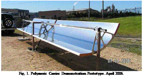 |
In the initial prototype (which was developed purely as a demonstrator) the structure providing and supporting the parabolic shape was intended to take the entire load on the collector. Refer to Figure 1.
During the detailed development phase it was proven that a large volume of polymeric foam material with a layer of structural skin could provide the structural integrity required. Various polymeric foam materials and structural skin materials were investigated for this purpose. Many previous attempts in manufacturing concentrating collectors using polymeric materials have failed due to the lack of long term form stability of many polymeric core materials. Form stable polymeric core materials do exist but are very expensive in volume. The concept was abandoned due to the high cost.
With a focus on reduced overall cost, a final configuration was devised whereby each component in the system had a specific objective, and the optimum geometry for each component was chosen. This lead to the choice of a single torque tube with sufficient stiffness to carry the torsional loads of the system, and a simple sandwich panel rigidly mounted to the torque tube which would provide sufficient bending stiffness to maintain the parabolic mirror surface. Mounting arms for the receiver tube were to be mounted directly on the torque tube, and the torque tube itself would also function as the rotation shaft of the system. The possibility of counter balancing the system was
also analysed and found to be cost effective as it reduced the torsional load on the system which improved the system optical performance.
This resulting system has a relatively low surface area to be laid up, has sufficiently thin core material that pre-forming the core would be reduced or eliminated, and can be packed efficiently for shipping. Furthermore, the system is readily scalable, can be produced in modules, and can utilise standard off the shelf components for mountings, shafts, bearings. On site assembly of components, and reduced component weight were also favourable, and the system also allowed for reduction of the gap between panels adjacent to the actuation cylinder.
The team developed a unique technique to form and bond the reflector (speciality aluminium mirror using physical vapour deposition (PVD) to obtain the reflectivity or speciality silvered glass mirrors) to a structural carrier in a one step manufacturing process using composite materials. The carrier consists of an efficient sandwich structure of fibre-reinforced polymeric skins and a specialised core material. Furthermore due to the excellent bond between the carrier and the mirror, the mechanical properties of the mirror are integrated into the strength and stiffness of the carrier. This process results in a lightweight, stiff and accurate surface. The use of specialised materials also provides a form stable carrier, overcoming problematic creep experienced when using low cost inferior core materials and manufacturing techniques.
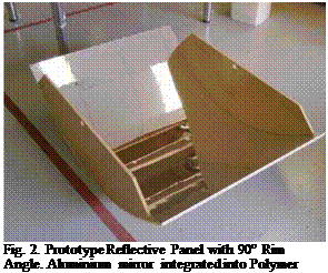 |
After a number of iterations with processes and materials the team successfully manufactured small prototype reflective panels with a 90° rim angle (RA) as shown in Figure 2.
Finite element (FE) analysis of the 90° rim angle collector was undertaken which considered representative wind loads that induce bending and torque. The analysis was based on 12m/s wind speed with allowable deflection limited to 0.5° over a 10m representative trough length.
Remaining torque and bending moment loads were considered to be born by the steel torque tube/counter-weight combination as opposed to the shell and thus could be excluded.
The optimum core thickness for the composite sandwich laminate of the PTC shell was calculated to be approximately 6mm. The design called for vacuum resin infusion processing of the laminate. This was first employed on the 90° RA prototypes. Commercially available core of 10mm thickness combining a grooving pattern on its surface for vacuum resin infusion was sourced.
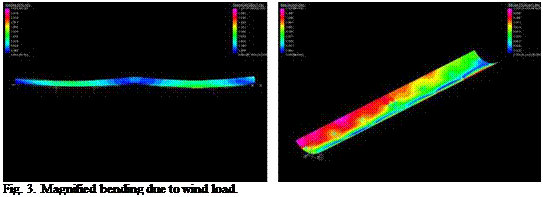 |
When a subsequent decision was made to open up the rim angle to a flatter 50 degrees due to receiver re-design, the10mm core thickness choice proved useful by offsetting the reduction in stiffness caused by the reduced shell curvature and obviated the need for further FE analysis. Subsequent field trials of the manufactured prototypes confirmed this course of action. Representative FE plots of the 90 degree RA geometry are illustrated in Figures 3 and 4, firstly for magnified bending and then for magnified torque (twisting).
Fig. 4. Magnified twist due to wind load.
Several subtle but significant composite laminate modifications were evaluated in the numerical modeling and on the physical 90° RA prototypes before settling on the chosen lamination sequence. The laminate schedule features the aluminium mirror surface on the mould side which is also considered structurally effective, combined with a composite sandwich laminate.
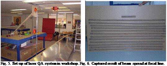 |
After the completion of the first of these full size reflective panels the team developed a laser measuring QA procedure to record the focal accuracy. The set-up of the laser is shown in Figure 5 and the results in Figure 6. This yielded pleasing results and generated the confidence to proceed with the remaining 7 prototype reflective panels.
To complete the design of the collector full 3D modelling and documentation of not only the parabolic reflector but also the associated steel componentry comprising the torque tube, bearings, drive system, receiver mountings, mounting legs and counter-weights etc. was conducted. This design step involved several iterations to reduce cost. The solar tracking system was developed in house and consists of a stepper motor driving through a reduction system and an extremely accurate inclinometer mounted directly on the collector. The system is controlled with a
proprietary embedded microcontroller and solar tracking algorithm. All components are sized to be economically packed into ISO shipping containers for transport and can be manually handled and easily installed on site
2.
 |
Key characteristics of the collector are
• 1.2 m Aperture by 6 m long parabolic panel elements.
• 4 panels per “standard” module — 24 m long modules.
• Torque tube is rotational axis.
• Counterweight balanced
• 50° rim angle chosen to suit a new shrouded receiver under development.
• Non-evacuated glass encased 25.4 mm stainless steel receiver with selective coating.
• 45:1 geometric concentration ratio.
• Expected maximum temp 220° C
The first test conducted on the collector was a photogrammetrical examination of the reflectors of the installed module. A surface was numerically fitted to the measured points from the photogrammetry. Using proprietary developed ray tracing software which included the Gaussian distribution of the solar disk, the CSIRO checked the accuracy of the collector. The results were very pleasing and mirrored closely the results obtained from the laser measuring QA process conducted earlier. Figure 8 shows a flux map developed from the ray trace 6 mm below the focal line of the parabolic trough. The results from the photogrammetry and laser QA confirmed the accuracy of the manufacturing process and installation.
|
1st International Congress on Heating, Cooling, and Buildings " ‘ 7th to 10th October, Lisbon — Portugal *
Fig. 8. Output from Photogrammetry test. Graphical representation of the flux density 6 mm below the focal line. |
The prototype field was integrated hydraulically (thermal oil) and for control (solar tracking) into the CSIRO Energy Centre solar facility. Each collector module was instrumented so as to measure the inlet and outlet temperatures of the thermal oil. The facility is equipped with a pyrheliometer and weather station and Direct Normal Irradiance and weather data is collected continually. The volume flow and temperatures of thermal oil are sampled and recorded at fixed interval (say 10 seconds). An electro-thermal heating element in the thermal system allows for the thermal oil to be raised to preset temperatures prior to the commencement of testing. This set-up was used to commission the collectors and conduct preliminary tests to determine the collector thermal performance. The preliminary performance test proved that the designed, manufactured and installed prototype was meeting or exceeding expectation. The tests also reinforced the need for more accurate temperature and flow measurement and assisted in establishing a robust data acquisition and analysis system. A test procedure was developed based on the ASHRAE Standard 93-2003 Methods of Testing to Determine the Thermal Performance of Solar Collectors. To satisfy the requirements of the test standard a method was needed to control the inlet temperature of the thermal oil. A portable test rig comprising a pump, flow meter, oil cooler, temperature controller and temperature sensors has been designed. Construction of the test rig is due to commence and formal thermal efficiency tests will be conducted thereafter. Final test results will be published thereafter.
1.1. Mechanism of solar desiccant cooling system
The detail schematic diagram of this system is shown in Figure 1. This solar desiccant cooling system is composed of two air handling units with two desiccant modules and is operated in regeneration process and in dehumidification cooling process at the same time while the operation
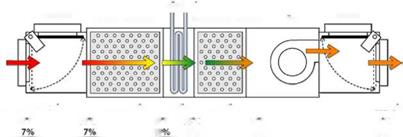
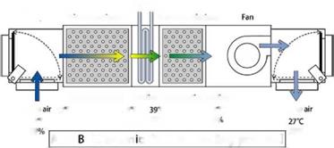 mode is switched. Each air handling unit is composed of a primary desiccant module, a cooling coil, a secondary desiccant module, a fan and two damper boxes to control air flow. The well water
COOlmg coil
![]()
Cooling coil
Fig. 1. Schematic diagram of solar desiccant cooling system.
is assumed as cooling water for cooling coils without a refrigerator. The rain water and the cooling tower can be used to cool the heated air for the cooling coil. The air flow rate of 1000 CMH is supplied by the one of the fan.
In regeneration process, the primary desiccant module (silica-gel) is regenerated by the collected hot and dry air and the collected hot and dry air become the little hot and humid air. The little hot and humid air become the humid air by the cooling coil. The second desiccant module absorbs the moisture of the humid air and the air is exhausted to outdoor.
In dehumidification cooling process, the humid fresh air is dehumidified by the primary desiccant module and is cooled by the cooling coil and the secondary desiccant module. The evaporative cooling is used by the stored moisture of the secondary desiccant module in regeneration process. The dehumidified fresh air is supplied to indoor.