Как выбрать гостиницу для кошек
14 декабря, 2021
The principle of the integration of the solar plant into the heating distribution system of the building is show in Figure 1. In winter the produced heat of the solar system is provided to the thermally activated ceilings with a maximum capacity of 200 kW on a low temperature level of 50/30°C. If the solar system delivers e. g. in autumn and spring more than 200 kW, the heating energy is switched to a higher temperature level and connected to the main heating distribution system of the building for the rest of the day. In summer the heat is directly provided to the main heating distribution system, which supplies the adsorption chillers with the required heating energy.
|
|
|
|

Heating distribution Chilled distribution
Figure 1: Hydraulic scheme of the solar adsorption cooling plant (FESTO AG)
The installation of the solar plant is supported by the German government within the Solarthermie 2000plus program and the monitoring system was installed by the University of Applied Sciences Offenburg [1].
The results obtained for the different simulations are summarised in the tables 1 and 2. They show the required solar collector surface to achieve the objective of 700 MWh/year of chilled water and
different energy performance parameters for the different thermal chiller and solar thermal technologies.
As expected, both tables show that solar collectors having higher efficiency parameters give a higher heating and cooling production per area unit. Also it could be observed that because of the lower operation of the solar adsorption systems, these have higher solar gain coefficients than the absorption ones. Alternatively, the specific chilled energy coefficients depends not only of the collector technology but also of the thermal chiller technology, being the best options the ab/adsorption systems with ETC-CPC collector with a maximum performance of 606 kWh/m2y for the combination with the BDH-65 chiller. The adsorption systems specific chilled energy coefficients only exceed the ones of the absorption systems when FPC collectors are used.
Comparing the Broad solar cooling systems themselves, the BDH-65 systems give a better performance than the BDH-50 ones, especially for ETC and FPC collectors. That fact leads to lower solar collector surface requirement to achieve the 700 MWh of chilled energy. The reason of that behaviour is the better annual average performance of the thermal collectors in BDH-65 systems. Looking at only to the adsorption results of table 2, the MYCOM ADR-60 SYSTEMS present better performance than the ADR-80. In that case the solar system has more or less the same performance and the explanation of this result is that the ADR-60 systems operate at slight higher temperatures in the generators-receivers, obtaining then slight higher values of their COP.
|
T able 1. Collector surface and energy performance parameters for different solar collector technologies and absorption chillers.
|
|
Table 2. Collector surface and energy performance parameters for different solar collector technologies and adsorption chillers.
|
Comparing this analysis to the previous study [3], it could be observed that the MYCOM ADR-80 results are very similar with differences lower than 3.5 %. In the previous study we used some empirical correlations to simulate that chiller. This entire means that the method suggested by Ktihn and al. [3] is valid to model this adsorption chiller. As regards the absorption chiller model, in [3] we used the Thermax LT 21 S with 739 kW with an average COP of 0.64. In the case we are dealing with now we selected the Broad chillers because they present a better COP (0.76). As a consequence, the values of the specific chiller capacity calculated now are between a 4 and 15 % higher. Obviously, the collectors’ surface requirements are also reduced in the same amount.
It should be remarked that, due to the special chilled water demand profile, the solar cooling system should be in operation the whole year. As a result the cooling water temperature is almost 2/3 of the year close to 22 °C. One of the most important consequences of working at lower cooling tower water temperatures is that the temperatures needed in the generator of the chiller could be lowered maintaining the capacity and then increasing the performance of the solar thermal field. In fact, the temperature in the generator can be as low as 60°C for adsorption and 85°C for absorption in the winter period.
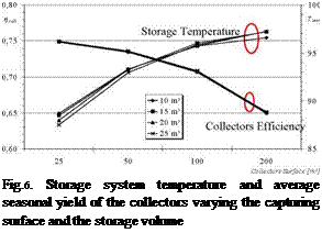
In Figure 6 temperature trends of the storage system and the average seasonal yield of the collectors varying the capturing surface and storage volume are reported. The average seasonal temperatures are always between 85°C and 100°C inclusive which correspond to average seasonal values of collector efficiency which varies from a minimum of 65% to a maximum of 75%.
In Figure 7 the trend of the average seasonal solar fraction is illustrated, defined as the seasonal refrigerant energy supplied by the absorption chiller compared to the seasonal refrigerant energy required by the building, equal to 31500 kWh cooling energy, varying the collectors surface
 |
![image249 Подпись: Collectors Surface [m2] Fig. 7. Average seasonal solar fraction varying the capturi ng surface and storage volume](/img/1154/image249.gif) |
and the storage volume. Such a parameter grows both with the capturing surface and with the storage volume, since it is possible to obtain higher inlet temperatures at the absorption chiller generator with consequent greater refrigerant energy provided. It is important to observe that the increase marked by the solar fraction is obtained by changing from 25 m2 to 100 m2 of collectors, while for surfaces greater than 100 m2 the solar fraction hardly increases. Despite the higher temperatures supplied to the generator, the solar fraction is in fact penalised by the operative limits of the absorption machine.
Finally, in Figure 8 the average seasonal performance coefficient trend of the absorption machine varying the capturing surface and storage volume is illustrated. The average seasonal COP varies between a minimum of 0.391 to a maximum of 0.437, from the reference value provided for the absorption chiller considered and equal to 0.60. Such a value is actually attainable in nominal operative conditions, with adequate inlet temperatures to the generator obtained by means of an auxiliary heater. The performance coefficient of the machine is penalised since the plant considered uses a traditional chiller instead of an auxiliary heater for the distribution of the refrigerant load which is not distributable by the absorption chiller.
![image250 Подпись: 0 50 100 150 200 250 Collectors Surface [m2] Fig.8. Average seasonal COP of the considered absorption chiller varying the capturing surface and storage volume](/img/1154/image250.gif) 0,44
0,44
C. O.P.
0,43 0,42 0,41 0,40 0,39 0,38
The energy performance of a solar energy system which uses a simple effect absorption chiller for the production of a refrigerated water flow rate used for the cooling of an open space environment by means of a radiant ceiling was analysed. The same solar collectors are used during winter for heating the same building, by means of the same distribution terminals. Heat pipe solar collectors were simulated by virtue of the elevated temperatures required for correct functioning of the absorption chiller Control logics were proposed which regulate the inlet temperature of the radiant ceiling, which permitted the evaluation of solar fractions obtained by the plant, based on
the capturing surface area and storage volume. It was observed that during winter, due to the high temperatures reached in the storage system, the collectors operate with limited efficiency yet the system is capable of supplying solar fractions close to 100% for capturing surfaces greater than or equal to 100 m2, independently of the storage tank volume. The high temperatures reached in the tank are opportunely regulated to supply the radiant ceiling, by means of a three way valve blending system which operates for long periods of time with high recirculation flows. The total yield of the system, due to the losses of thermal energy in the tank, assumes values equal to 30% for capturing surfaces of 200 m2, independently from the storage volume.
In summer, the system yield assumes values that are variable between 75% and 13%, due to the operative limits of the absorption machine which requires the use of an auxiliary chiller. It was decided to use an electric auxiliary refrigerating machine to supply the load that was not distributable by the absorption machine in that preliminary evaluations of primary energy consumption showed convenience compared to the use of an auxiliary heater usable to raise the temperature of the generator.
The solar fractions reached increase slightly for capturing surfaces greater than 100 m2, since they exceed the operative limits of the absorption chiller, principally represented by its insufficient flexibility, which makes the use of an auxiliary system necessary. For an capturing surface of 50 m2 and a storage volume of 25 m3 an average seasonal solar fraction equal to 30.6% is attained; the maximum value is 35.7% for a plant with 200 m2 of collectors and 25 m3 of storage. The refrigerant energy supplied by the absorption chiller hardly varies for capturing surfaces greater than 100 m2; for a storage volume of 25 m3 it is 10643 kWh with a surface area of collectors equal to 100 m2 while it is equal to 11185 kWh changing to an capturing surface of 200 m2, with an increase of 5% with a doubling of the capturing surface.
Finally, it is possible to observe the slight variability of almost all the analysed parameters compared to the storage volume; storage volumes greater than 10 m3 do not bring about benefits to plant performance but it is not possible to go below such values in order to guarantee system stability.
References
[1] Arcuri, N., Bruno, R., Ruffolo, S., 2005. Prestazioni termiche di sistemi di riscaldamento a soffitto radiante alimentati da collettori solari, Proceedings from the 2nd International CLIMAMED Conference, Madrid, March
[2] Lazzarin, R., Crose, D., 2000. Il soffitto radiante nella climatizzazione ambientale, SG Editoriali, Chap. 1
[3] TRNSYS, Reference Manual, AA. VV., 2001. A transient system simulation program, Solar Energy Laboratory, Madison, Wisconsin, USA
[4] UNI 10349, 1994 — “Heating and cooling of buildings; climatic data”
[5] Gansler, R. A., KleinS. A., 1993 “Assessment of the Accuracy of generated Meteorological Data for Use in Solar Energy Simulation Studies”, Proceedings of the 1993 ASME International Solar Energy Conference, Washington D. C.
[6] Oliveti G., Arcuri N., Bruno R., De Simone M., 2007 “Energy Performances Of A Radiant Floor Heating System Supplied By Solar Collectors With Ventilation Stream Heating By An Air To Air And An Air To Water Heat Exchanger”- REHVA International Congress — Helsinki [7] Oliveti G., Arcuri N., Bruno R., Mazzuca A., 2005 “Energy performance of an absorption chiller supplied by solar collectors in Mediterranean area”, SWC 2005, Orlando, USA
[8] UNI 10339, 1995, Air-conditioning systems for thermal comfort in buildings. General, classification and requirements. Offer, order and supply specifications.
[9] Lazzarin R., Castelletti F., Busato F., 2006 Soffitti radianti e aria primaria, Condizionamento dell’aria Riscaldamento e Refrigerazione N° 6
[10] Oliveti G., Arcuri N., Bruno R., 2008, Caratterizzazione di Soffitti Radianti che Impiegano Tubi Capillari per il Riscaldamento degli Ambienti” AICARR International Convention
[11] Arcuri N., Bruno R., 2005, Prestazioni termiche di sistemi di raffrescamento a soffitto radiante e relative strategie di controllo, 60° ATI National Congress, Rome
Marco Beccali, Pietro Finocchiaro, Massimiliano Luna, Bettina Nocke
Dipartimento di Ricerche Energetiche ed AMbientali (DREAM) — Universita degli Studi di Palermo
Via delle Scienze bld. 9 — 90128 Palermo, Italy — tel +39091236211 — Fax +39091484425
Corresponding Author: marco. beccali@dream. unipa. it
Abstract
The paper concerns the first monitoring results of a solar DEC system that has been installed at the end of 2007 at the DREAM Department, Universita degli Studi di Palermo, Italy. The system is mainly composed of a desiccant cooling unit for primary air treatments specially designed for application in humid climate, a liquid solar collector system and a radiant ceiling. The system is fully operating since March 2008 and first summer operation results and evaluations are already available. The monitoring results have been aggregated in terms of COP of the desiccant cycle, fraction of the total cooling energy covered by the desiccant cycle and primary energy ratio. They are fairly good and reasonably comparable to the simulation results previously conducted in the design phase. In particular, the monitoring of the system has shown interesting results especially for what concerns the heat recovery from the condenser side of the water chiller used to feed the radiant ceiling and the auxiliary cooling coils. On the other side, some improvements are still necessary, such as air leakages reduction in the heat exchanger, check of some relative humidity measurement points, optimization of set points for auxiliary coils and supply humidity control.
Keywords: Desiccant cooling, radiant ceiling, heat rejection, monitoring results
Several studies show that desiccant cooling system have a limited dehumidification potential for given characteristics of the desiccant rotor, regeneration temperature, flow rates and so on and that auxiliary cooling power for dehumidification is required to fulfil the desired supply air conditions. In addition, the humidity ratio of outside air for the considered location can be very high in summer season (over 20 g/kg). Therefore, particular interest was set to the dehumidification performances of the system. Moreover, the system can be tested in different internal latent load conditions by means of adjustable humidifiers, in order to simulate different occupation patterns.
Another key issue of the set-up is that the heat rejection of the chiller is partially utilized in a heating coil displaced in the AHU return air path for regeneration purposes, allowing a reduction of the required solar field area.
It is known that the energy saving potential of solar cooling systems can be very dramatically affected by higher electricity consumption for auxiliary equipment (fan, pumps, etc) in comparison to the one of conventional systems. With this aim, a detailed monitoring of electricity consumption for ventilation, chiller and auxiliaries was performed.
The system is composed of a desiccant cooling unit for primary air handling (AHU) equipped with liquid solar collectors and coupled with a radiant ceiling. The AHU provides fresh air to a room of 450 m3 used as a laboratory for modelling and testing of solar cooling systems. Also the performance of the desiccant AHU in combination with the radiant ceiling can be investigated, with the aim to maximize the specific cooling power of the radiant ceiling in different load conditions. Figure 1 shows the system configuration and its main component.
SOLAR COLLECTORS 22.5 М2
STORAGE 600 LT
RAD ANT
CEILING
EXTRACTED
AIR
RETURN
SUPPLY
A R
OUTS DE
EVAPORATING
Fig. 1. Functional scheme — summer operation
The desiccant cooling unit provides air change and dehumidification by means of a desiccant wheel regenerated both from solar collectors and rejected heat of the chiller. If the humidity ratio and/or temperature set point of supply air is not met, further dehumidification and temperature decreasing can be achieved by means of two auxiliary cooling coils. In particular, the first coil CC1 is utilized for predehumidification purposes, whereas the second one controls the air temperature if the indirect evaporative cooling is not sufficient to reach the desired supply temperature. The radiant ceiling provides to meet the sensible loads.
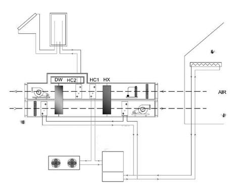 The control of the AHU in cooling cycle has four operation modes. The system starts in the ventilation mode, where no active air handling is performed, but only the fans are switched on (mode 0). In mode 1, only indirect evaporative cooling is performed by means of a heat recovery wheel HX and the humidifier on the return side. In mode 2, the solar desiccant cooling cycle is operated by means of the desiccant wheel regenerated by the heat coming from solar collectors and the condenser of cooling
machine. In mode 3, the auxiliary back-up coils are activated to meet the cooling loads in case the desiccant cycle is not sufficient to reach the desired supply air conditions.
As already mentioned, a thermodynamic heat recovery is achieved by means of the condensation heat of the water chiller feeding the radiant ceiling and the auxiliary cooling coils. The heat rejected by the chiller can be used on the return side process to preheat the regeneration air stream [1, 2, 3]. The condensation coil HC1 allows a preheating of the regeneration air stream increasing its temperature of about 12-15°C. An external condenser connected in series to this coil provides for the remaining condensation of the refrigerant of the vapour compression cycle. A further advantage of this configuration is also the good time correlation between the cooling power demand and the heat rejection at the condenser. Further temperature rise up occurs in the solar collectors loop in order to reach regeneration temperatures of 65 — 70°C at the inlet of the desiccant rotor. Due to the higher chilled water temperature required both by the chilled ceiling and auxiliary cooling coils (about 12°C), an increase of the cooling capacity and COP of the chiller can be achieved. A heat storage tank of 0.6 m3 balances the heat produced by the solar system and the heat supplied to the coil HC2. The following table shows some relevant technical data.
|
Table 1: Design data
|
A more detailed description of the plant in terms of control issues and monitoring system can be found in a previous work of the same authors [4].
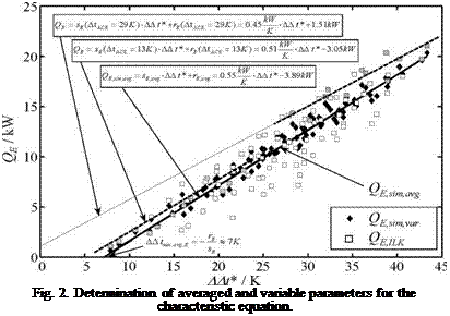 |
In Fig. 2 the cooling capacity of the ILK test data is shown as function of AAt*. The modified characteristic temperature difference AAt* has been calculated from the arithmetic means of the measured inlet and outlet temperatures assuming a constant Duhring parameter (5=1.15). In addition Fig. 2 depicts the results of a linear data fit with constant and variable characteristic parameters sE and rE. For the determination of the variable parameters sX and rX the data have been grouped into five classes between the minimum and maximum temperature lift included in the ILK data base. In Fig. 2 only the groups with lowest and highest temperature lift (AtACE = 13±2 K and AtACE = 29±2 K) are high-lighted with grey symbols to illustrate the variation of sE, rE and, AAtmin, respectively. If only these two groups are used, the coefficients sE1 and sE0 for the linear dependency of sE(AtACE), in equation (6) can be found from the upper two equations in Fig. 2. However, for the parameter list of Type 177 all five groups of AtACE-intervals have been used as supporting points in a linear least square fit to determine all the values sX,1, sX, o and rX1, rX,0.
As seen from Fig. 2 the general trend of the cooling capacity is predicted correctly when calculated by the characteristic equation with constant (solid line) or variable (closed symbols) parameters. If the variable parameters are used, also the scatter of the measured data is reproduced slightly better. Nevertheless, a relatively large deviation remains. This may be an effect of measurement uncertainties and / or different methods and time intervals of chiller evacuation during the test procedure. These effects are not included in the method of characteristic equations.
This task is divided in work packages born from the difficulty in comparison of the newly developed machines. Not all systems existing in the market are able to be tested with the published norms created some years ago for great capacity sorption chillers producing 7 °C water with the classical temperature levels in the generator and condenser, not only because of the sizes but also for the different technologies that are going to be taking into account, absorption cycles, adsorption and ejectors.
Nominal Coefficients of Performance (COP’s) of this new machines are being measured at different temperature levels depending on their final use. This means, that results are not directly comparable among them, due to the diversity of nature of values. Therefore, a new way to compare them based on the apparatus and the complete system performance is needed.
As the COP’s of the machines themselves are being calculated, also the efficiencies of the facilities should be determined due to the number of pumps and different equipments needed.
Furthermore, a parametrical study with the different energy supplies that can be used must be done, which may range from solar thermal plants to district heating and waste heat sources etc.
District heating systems can be connected to TDHP (i) in winter time to heat with an incremented performance and (ii) in summer time to cool — keeping more stable the heat demands from the point of view of the production. As can be seen in the figure3, presented in the 2nd workshop meeting (Zurich, 20th May,08) during the months of July and August, the heat demands decreases to a 15% of the nominal one, creating a yearly overall inefficiency in the design of the system and the distribution of that heat. With an existing demand to produce cold in these summer months, the differences between summer and winter will decrease.
|
Fig. 3. Demand profiles of four installed District Heating Systems in Germany. |
Collaborating with the Task38, the use of solar energy as the energy vector which drives, or helps to drive, the TDHP is being studied. In this case, solar radiation will be used during the winter as low level input for the heat pump, highly increasing the efficiency of the collectors, although the amount of radiation in certain climates will not be so much. Previous calculations in [6] have been done in order to explain this.
Depending on the final distribution systems (i. e. Fan coils, radiant ceilings and floors, etc) will be need as an output of this task a new methodology to label and recommendations for test procedures where it will be taking into account the different temperatures for heating and cooling, COP’s, energy consumptions, CO2 production, exergies, etc.
The most common recent-built-housing in southern Spain could be classified into three typologies:
• Multi-family building with six 60-square-mettered apartments
• Single-family 120-square-mettered terraced house
• Single-family 400-square-mettered detached house
There are many differences between the three housing typologies listed. From the point of view of cooling, the most remarkable differences are those related to the simultaneousness factor and the level of comfort required in each one.
1.1. Traditional cooling technologies
Up to now, the domestic systems most frequently installed in Spain have been mono or multi-split mechanical vapour compression systems, due to its modularity, price and technical development. Other solutions, such as centralized chillers, have been used for large-surfaced housings, but are not very common for domestic purposes.
When the authors set forth to develop a parabolic trough collector system especially targeted at commercial buildings the following design criteria were seen as important:
• Aesthetic appeal with low height
• Modular system allowing also small fields (say as small as 50m2) to be economically viable
• Easy to install; not requiring special tooling or lifting equipment
• Accommodate alternative layouts and orientations on complex roof geometries
![]() 1st International Congress on Heating, Cooling, and Buildings 7th to 10th October, Lisbon — Portugal *
1st International Congress on Heating, Cooling, and Buildings 7th to 10th October, Lisbon — Portugal *
• Light weight for roof mounting with few foundation points
• Accuracy and stiffness to ensure high performance
• Cost competitive on a $/kWh level
• All components shipped in 20 ft ISO sea containers
H. Roh1*, K. Suzuki1 and M. Udagawa2
1 OM Environmental Planning, 4601 Murakushi-Cho, Hamamatsu-City, Shizuoka-Prefecture, 431-1207,
Japan
2 Kogakuin University, 1-24-2 Nishi-Shinjuku, Shinjuku-Ku, Tokyo, 163-8677, Japan
* roh@omsolar. jp
Abstract
This paper describes the development and the field test of a solar desiccant cooling system for small office building. The main purpose of this system is the process of the fresh air heat load and the getting cool to dehumidify the fresh air. This system is composed of two air handing units with two desiccant modules and is operated in regeneration process and in dehumidification process at the same time while the operation mode is switched. Solar heat is used for the regeneration of desiccant module and well water is used for cooling the air passed through the desiccant module. From the monitoring results, the fresh air heat load of 73% was reduced by the effect of the solar desiccant cooling system. From the field test results, it was found that the reduced daily electric power consumption of the electric heat pump air conditioner (EHP) was 36% for the operation of the solar desiccant cooling systems compared with the operation stop. In winter, these solar desiccant cooling systems are used for the solar space heating systems. From the field test results in winter, the reduced daily electric power consumption of the EHP was 40% for the operation of the solar space heating systems compared with the operation stop.
Keywords: solar thermal, desiccant, cooling, well water
The common air-based solar thermal system is useful for space and DHW heating, whereas the collected solar thermal energy is almost exhausted to outdoor except heating DHW in summer. For using the solar thermal energy available throughout a year, the solar desiccant cooling system has been developed for the pre-cooling system of fresh air to dehumidify fresh air with ventilation in summer. In addition, this system is used for solar space heating system to heat fresh air with ventilation in winter. This system was installed at the field test office building in the central area of Japan. The mechanism of the solar desiccant cooling system and the results from the field test is introduced.
The schematic of the regenerative evaporative cooler fabricated for the application to the desiccant cooling system is shown in Fig. 3. The regenerative evaporative cooler is comprised of multiple pairs of the dry and wet channels as shown in Fig. 3. A representative single pair of the channels is displayed in Fig. 3(a). The two channels are separated by a thin flat plate and metal fins are inserted into both the channels to extend the contact surfaces improving the compactness of the cooler. A guide channel is attached at the bottom end of the wet channel to prevent mixing between the process air inflow and the extraction air from the wet channel.
The regenerative evaporative cooler was built by compiling multiple of the single pairs. The detailed geometric configurations such as the frontal area, the number of pairs, the fin height, the fin pitch, etc. were determined through numerical simulations on the heat and mass transfer in the channels to meet the cooling requirement.
Portugal *
![]()

 dry channel
y V*
wet channel
extraction air
guide channel
(a) single pair of the channel (b) assembly of multiple pairs
Fig. 3. Fabrication of the regenerative evaporative cooler.
The regenerative evaporative cooler was tested in a climate chamber for the cooling performance evaluation at various inlet temperature and humidify conditions. The flow rates of the two air streams, i. e., the process air and the extraction air, were measured at the outlets of each channel. The temperature and the humidity were measured at both the inlet and outlet. The energy balance was examined by comparing the enthalpy changes in the two air streams and was found within 10% error for every test case.
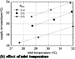
The representative test results are displayed in Fig. 4. The tests were carried out at the flow rate of the inlet air of 20 CMM and the extraction ratio of 0.3. When the inlet air is at 32oC and 50%RH, the outlet temperature is found about 22oC showing the cooling effect of 10oC. This outlet temperature is even lower by 2oC than the inlet wet-bulb temperature which is the lowest temperature obtainable in a direct evaporative cooler. Furthermore, comparing with the adiabatic process in the direct evaporative cooler, the cooling in the regenerative evaporative cooler is substantial, since the cooling is obtained without an increase in the humidity. The outlet temperature is also shown to decrease as the inlet humidity decreases. This is because the water evaporation becomes more active to increase the cooling effect as the air becomes dryer.
2.
 |
 |
Fig. 4. Cooling performance of the regenerative evaporative cooler.
A desiccant rotor was fabricated using the polymeric desiccant newly developed in Korea Institute of Science and Technology (KIST)[9]. This polymeric desiccant is developed by ion modification of super absorbent polymer (SAP) and is named as super desiccant polymer (SDP) for its superior moisture sorption capacity 4~5 times larger than those of conventional silica gels. It is also known that SDP can be regenerated even at the relatively low temperature of 60 ~ 80oC.
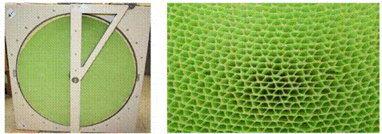
To fabricate the desiccant rotor, firstly the SDP was prepared by ion modification of SAP and laminated by coating the SDP on a 0.1 mm thick polyethylene sheet. Then the sheet was corrugated and rolled up into a rotor. Figure 5 shows the completed desiccant rotor framed into a cassette.
The diameter, the depth, the dimensions of the corrugated channel, etc. were pre-determined from numerical simulations on the heat and mass transfer in the desiccant rotor.
The dehumidification performance was also tested in a climate chamber. The flow rates of the two air streams, i. e., the process air and the regeneration air, were measured at the inlets of each channel. The temperature and the humidity were measured at both the inlets and outlets of the two air streams. The energy balance was examined by comparing the enthalpy changes in the two air streams and was found within 10% error for every test case. The moisture balance between the two air streams was also found within 10% error for every case.
Figure 6 shows the dew-point temperature depression and the temperature increase of the
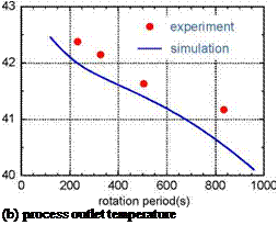
 |
|
(a) dewpoint depression
Fig. 6. Effect of the rotation period of the desiccant rotor.
process air through the desiccant rotor. The relevant tests were carried out at the process air inlet temperature of 32oC, the regeneration air inlet temperature of 53oC, and the inlet dew-point temperature of both the process air and the regeneration air of 18.5oC. As shown in Fig. 6(a), the dew-point temperature depression is maximized at a certain rotation period of the desiccant rotor, which implies the dehumidification performance is optimized at the rotation period. When the rotation period is excessively short, the moisture sorption of the desiccant is not effective because there is not enough time for the desiccant to be cooled from the regeneration temperature down near to the temperature of the process air which is necessary for the desiccant to absorb moisture from the process air. In the meanwhile, when the rotation period is excessively long, the moisture sorption is not effective either because the desiccant becomes saturated with moisture resulting in a decrease in the moisture sorption capability. In these reasons, there comes to exist an optimum rotation period of the desiccant rotor. In the desiccant rotor developed in this study, the optimum rotation period is found about 500 seconds at the regeneration temperature of 53oC. It was found from further experiments that the optimum rotation period tends to decrease as the regeneration temperature increases. Meanwhile, the outlet temperature of the process air decreases monotonically as the rotation period increases.