Как выбрать гостиницу для кошек
14 декабря, 2021
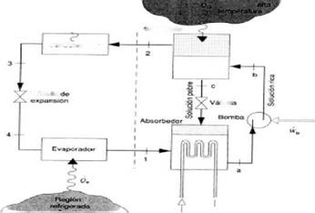
Fig 2 illustrates the cooling system for the office and seminar rooms as well as for the server room. Office and seminar rooms are supplied with fresh air via a ventilation system, in which cooling coils are integrated to transfer the cold to the rooms. During working hours, an average air change
of 0.85 was assumed, outside of working hours, only the constant infiltration rate of 0.15 was considered.
For the server room, both a recirculation and a fresh air ventilation system were integrated. The cold production system itself was designed as a solar air conditioning system. From all the different technologies available for heat driven cooling systems, an absorption chiller with a capacity of 50 kW for producing cold water was used and integrated into the system model [6]. In addition, heating, cooling and re-cooling circuits are completing the solar air conditioning system. The heating circuit consists of a solar collector field, a heat storage tank and a thermal back-up heater. The main component of the cooling circuit is a cooling coil for the supply of the building and the server room with cold. For this, the cooling energy is taken from a cold water store. As recooling, a wet cooling tower was used.
|
Fig. 2: Schematic of the cooling system |
The cooling system is controlled depending on the temperatures in the building as well as in the server room. Within the office and seminar rooms, the active cooling system operates when the temperature exceeds 26°C For the server room, two different cooling modes have been implemented:
■ In case that the ambient temperature is significantly below the desired server room temperature of 23°C, a fresh air ventilation with an air change of up to 60/h is applied.
■ In case of higher ambient temperatures, the recirculation system in combination with the cooling system is used.
2. Results
2.1. Summer measurements
During most of the monitoring periods the exterior temperatures were below 20°C, approximately 35%-45% of the time. The monitoring periods corresponding to measurements performed in housing units 8, 9 and 10 showed temperatures below 20°C during 25% of the time, and the ones corresponding to 6 and 2 during a longer period of time (45%-50% of the time).
In the majority of the monitoring periods the exterior temperatures were between 20°C and 25°C (comfort) approximately 40% of the time; between 25°C and 27°C (near to comfort) approximately 9% of the time, and between 27°C and 31°C approximately 10% of the time. The periods corresponding to housing units 3, 8, 9 and 10 presented exterior temperatures between 27°C and 31°C during the longest periods of time (11% -16% of the time); and the ones corresponding to housing units 4 and 11 during the least time (3% — 6% of the time). Therefore, in a general way the exterior temperatures were below 25°C during the different monitoring periods in close to 70%- 85% of the time. Thus, the other temperatures, above 25°C, are distributed in the remaining 15%- 35%. For the Fig. 6 it is possible to conclude that none of the monitored compartments during the summer 2007 months showed temperatures below 20°C.
The compartments that showed temperatures between 20°C and 25°C were mainly the ones with glazing areas oriented practically east, north and west (on average 6%-9% of the time). The compartment of dwelling 1, with glazing areas practically South+East, also showed temperatures between 20°C and 25°C in close to 13% of the time, while a compartment practically to the north in the same dwelling showed temperatures in these values approximately 41% of the time. Some compartments presented temperatures between 25°C and 27°C most of the time. These were those with glazing areas oriented practically to the north. Dwelling 10 presented temperatures within these values practically 85%-95% of the time.
Is noted that the housing units (7, 8, 9, 10 and 11) of the Building Alcantara-Rio, the only that have exterior shading systems of the blind type (beside a horizontal shading) most of the time showed temperatures between 25°C-27°C and 27°C-29°C, 92%-100% of the time. Being that the compartments with glazing areas to the: South presented temperatures between 27°C-29°C approximately 87% of the time; north showed temperatures 25°C-27°C approximately 90% of the time; west presented temperatures of 27°C-29°C approximately 35% of the time and temperatures of 25°C-27°C approximately 60% of the time.
The monitored housing units in buildings Pertejo (2, 3, 4, 5 and 6) and Navitejo (living room) without exterior shading presented temperatures practically distributed between 25°C and >31°C. The compartments with glazing areas practically east showed temperatures above 27°C approximately 67% of the time. Housing units 2 and 3 presented temperatures above 27°C in approximately 75%-95% of the time, with dwelling 2 presenting temperatures above 29°C over 40% of the time. In Fig. 7 refers to the mean temperature values and it was concluded that:

Mean of the mean temperatures: were above 25°C for all the monitored compartments with respective monitoring periods, being that for the majority of these it was approximately 27°C. In some studied compartments with glazing areas practically to the south (South, SSE, SSW) the mean temperature was close to 28°C. The studied compartments with glazing areas practically to the north (North, NNE) were the ones showing lower values of the mean temperature, close to 25,5 °C.
Mean of the maximum temperatures: for the different compartments in the respective monitoring periods were close to 0,5°C to 0,9°C higher than the mean temperature. Therefore, for most of the monitored compartments the average of the maximums was approximately 28°C.
Mean of the minimum temperatures: were close to or higher than 25°C for all the housing units in the respective monitoring periods. The average of the minimum temperatures was close to 27°C for the compartments with glazing areas practically to the south, while for the compartments with glazing areas practically east and west was approximately 26°C and for those with glazing areas practically to the north was approximately 25°C.
The exterior thermal amplitude varied practically between 15°C and 25°C in the different monitoring periods. The greatest external amplitude was obtained during the measurements performed in dwelling 1 (23°C), while the lowest was obtained during the measurements performed in dwelling 4 (10°C).
The greatest interior thermal amplitudes were obtained during the measurements performed in the compartments that kept the windows open during a good part of the time, even during daytime, like: the compartments in dwelling 5 (east), living room of dwelling 8 (west) and the bedroom in dwelling 4. Generally, the interior thermal amplitude for most of the compartments was of approximately equal to 5°C. Most compartments of the housing units 7, 8, 9, 10 and 11 present low thermal amplitude values, on average 3,5°C. These flats belong to a set of buildings that have exterior solar blind-type protections that permit greater flexibility, control and adaptation to the exterior conditions.
In Europe, the illumination from the point of view of work is defined according to the Daylight Factor, DF, which can be calculated according to two methods, the one established in a experimental way by data of n-site date under covered cloconditions and the other one defines defa theoretical way under clear sky conditions. But in every each the requirements fixed from for thctor are established for the mainland France metropolitoto be ahe climate of the islaon. Indeed, the FLJ DF deteed by the International Committee of Lighting, sets under the conditiskyconditio the available illumination inside the room and outside. The factor of comparison obtained is called Daylight Factor and expresses itself in percentage.
The following table [5] gives the percentage of time where three values of outdoor illumination are met during a typical year. In France, the value of 5000 lux is preferred in the calculations. The DF value of reference applied in France is 2.5 % [3] under cloudy sky conditions. This rule is not
adapted to tropical conditions with a mean illuminance much pore important compared to mainland France. DF values of 1.5 % are recommended by Adelard [2] so far.
|
Eext = 15 000 lux |
Eext = 10 000 lux |
Eext = 5 000 lux |
|
|
La Reunion |
87% |
92% |
>95% |
|
Guyane |
96% |
95% <… >100% |
95% <… >100% |
|
Mainland France |
55% |
72% |
87% |
|
Table 2 : Percentage of time for three outdoor illumination levels in the French overseas territories and in mainland France. |
It turns out that the criterion of the only daylight factor is not sufficient to characterize the performances in daylighting. The percentage of autonomy in natural lighting proposed by Reinhardt seems more adapted. These choices fit with the objectives of the task 31 of the International Energy Agency concerning the establishment of performances and strategies in the daylighting design in buildings [6].
2. Methodology
The heating system of the building is designed as the combination of the following installations:
• Radiant floor warming.
• Solar thermal panels.
• Biomass boiler support.
• Hot air support for rooms of general use from photovoltaic panels installed in walls.
The installation of 30 solar thermal panels (70 m2 effective surface, approximately) will provide 56% of the energy demand of the building. A biomass boiler will work as energy support equipment. Besides, the air flow along the back side of the photovoltaic panels installed as a chimney on the South facade will serve as supplementary heating system in winter. On the other hand, the thermal energy obtained from the photovoltaic panels will be transferred to the surroundings, according to the principles of Trombe walls.
Thermal energy supply to the building will be made by radiant floor warming, which is currently considered to best approach the ideal heating profile, since it provides very high efficiency and maximum thermal comfort.
Figure 5 shows values for energy supply of photovoltaic panels.
|
1.1 PV Facade
The PV facade has 76 multicrystalline silicon modules BP3160, with a total peak power of 12,16 kW and an area of 95,6 m2.
The direct current (d. c.) produced by the PV generator will be converted to alternate current (a. c.) with three inverters Fronius IG 40. Each inverter have a nominal power of 3,5 kW, a maximum efficiency of 94,5 % and an European efficiency of 93,5 %.
|
Table 1. Facade — PV Modules configuration
|
|
|
Fig. 2. PV Facade system configuration.
Windows have a much higher U-value than the opaque envelope and are therefore likely to account for high heat losses/gains. Conversely, its transmittance allows solar gains to enter the building, contributing to the heating loads in the cold periods. High levels of insulation can be achieved with several numbers of panes, low emissive coatings and gas filled cavities, or with new materials such as the aerogel. During the night period, when temperatures drop, the use of movable insulating systems prevents further heat losses. Over the summer, solar gains should be avoided. Passive solutions may include overhangs, reveals, movable shutters or blinds.
The quantity of radiation incident on the facade varies with the time and day of the year. Designing for solar gains strongly depend on the orientation, site layout and sunlight availability.
There are a number of different approaches to passive cooling design. They may involve buoyancy and cross ventilation, night ventilation usually associated with strong inertia, ground cooling, evaporative cooling and night sky radiation.
Throughout Europe, a relatively large diurnal swing in air temperature creates the possibility of night time ventilation to cool the building’s heat storage capacity, delaying its release to the space, as well as reducing temperature fluctuations. The ground below 3-4 meters has a relatively stable temperature which may be used to cool or pre-heat the air or a fluid passing through buried pipes. Its strong inertia may also be used for heat storage.
Although night sky radiation can promote cooling of the roof surface, this is rarely used in cities due to the pollution and the greenhouse effect which significantly reduces the radiation exchange to the atmosphere. Conversely, evaporative cooling is commonly found in traditional architecture, particularly in dry and hot climates of southern Europe. Some strategies of indirect evaporation allow its use in more humid climates.
 |
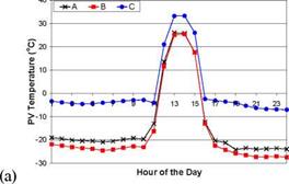 |
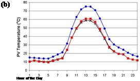
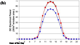
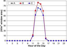
Fig. 3 presents the PV cells temperature for the three configurations studied for a sunny winter and summer day in Yellowknife with leeward wind. As it can be observed, the PV cells temperature in configuration A and B are very close since the PV laminate replaces the outer pane in both cases. For the winter day, the maximum PV cells temperature difference between configuration C and configuration A or B is of approximately 12oC during daytime. For the summer day, this difference is of about 16oC. The DC electrical power produced by the PV cells for these 2 days is presented in Fig. 4. The graphs reveal that the power generated by configurations A and B is very similar, but at peak sunshine hour, approximately 14% and 20% greater than configuration C for the winter and summer day, respectively. This can be explained by the higher cells temperature and the fact that less radiation strikes the PV cells in this configuration because of the outer glazing layer reflecting and absorbing part of the incident solar radiation.
 |
|
 |
|
Fig. 3. PV cells temperature for a winter day (a) and a summer day (b) in Yellowknife.
Fig. 4. DC electrical power for a winter day (a) and a summer day (b) in Yellowknife.
New York City is experiencing an unprecedented construction boom. With additional projects in the pipeline — such as the rebuilding of the World Trade Center site and various other major projects underway throughout NYC — this is a unique time to look at how the use of Building Integrated Photovoltaic (BIPV) systems may have an impact on the City’s future skyline. One of the main drivers attributed to the growing interest in BIPV systems is NYC’s challenge to meet growing peak electricity requirements. NYC is an electric ‘loadpocket’. It is geographically isolated — consisting of 3 islands and a peninsula — yet it has a peak demand of well over 10,000 MW. To maintain voltage support and reliability standards, the New York Independent System Operator (NYISO), which manages NY State’s bulk power transmission system and wholesale power markets, has determined that NYC must be capable of generating 80% of its peak electric power requirements within the 5 boroughs that make up the city. However, power plant siting has generally become more difficult and this is especially true in NYC, where real estate options are constrained, real estate values are high and community values overlap. [2]” In addition to the challenge of power supply,
[3] Introduction
An interactive wall is a building’s external wall, which reacts to weather conditions and transforms them according to user’s requirements. It is an important element of the indoor environment’s control system and, in consequence, for energy management of the whole building. The inputs of the interactive wall system include weather parameters, independent of human will and impossible to predict in the long term. Outputs include parameters of the indoor environment. They vary for different kinds of human activity and change during the whole day or over different seasons. Both the inputs and the outputs of the system are changeable, although in different ways. The understanding of this model is necessary to realize that the interactive wall system is very complicated and difficult to implement in practice.
[4] Natural ventilation
For a systematic process of evaluation a flow chart (see Figure 1) has been developed showing the logical sequence of worksteps to be carried out.
 results
ok?
![]() ^Jistof risks^)
^Jistof risks^)
recommendations
Fig. 1. Flowchart for the evaluation system
At first boundary conditions and minimum requirements (ko-criteria) are defined. Building type, location and especially the type of use were among the various criteria to be considered for the fa? ade.
The facades to be evaluated are classified by means of a “morphological box” for variations of design parameters such as shape, orientation of windows, construction, material, properties of opaque and transparent building elements, ventilation as well as cleaning and maintenance. In total, the “morphological box” has 23 fa? ade parameters, each of which has up to six variation steps.
Following the flowchart, an initial evaluation test has to be carried out to determine whether the fa? ade under consideration fulfills the compulsary minmum requirements. A list of possible problems can be made. If all boundary conditions and ko-criteria are fulfilled, then the more detailed evaluation can start. If otherwise, the fa? ade under consideration does not meet the first conditions, even with some possible improvements, then it will be taken out of the evaluation system.
The previous section has shown that it is possible to comply with the energy requirements of the RCCTE even without solar thermal collectors for domestic water heating. Yet, two important questions remain.
One is whether the use of solar thermal collectors, mandatory by the RCCTE, can be discarded for historical areas based on a criteria of “justified esthetical incompatibility”. According to the law, it is up to the licensing authorities (generally the municipalities) to judge this justification. The authors will take no definitive position here, although they admit that in some cases the relief from compliance may be justified.
The second question is, regardless of the answer to the previous paragraph, what is the energy relevance of the collectors if they are indeed applied, and its consequences in terms of energetic classification — especially its relevance to achieve class A+. This assessment was made by analysing a case with the same envelope and constructive solutions of table 8, but now adding solar collectors of medium performance (n0=0.73; ai=5.0 W/m2K; a2=0.05 W/m2K) for heating of the domestic hot water, maintaining the gas boiler as auxiliary system. As prescribed by the regulation a collector area of at least 1 m2 per person was considered. Table 9 shows the results of this exercise, which shows that by adding the solar thermal collectors the buildings now fall within class A. This strong effect is easily understood if we recall eq. 1 which shows that the primary energy consumption Ntc strongly values the energy consumption for domestic hot water when compared with the consumption for heating and for cooling.
4. Conclusions
Portuguese thermal regulation for residential buildings, the RCCTE is applicable to all new or significantly retrofitted buildings. It foresees the possibility that for buildings in historical areas certain requirements of the regulation may be discarded if an incompatibility with the architectural
frame are found and duly justified. An analysis to 6 apartments undergoing a retrofitting process in the downtown area of Porto (the “Ribeira”- classified by UNESCO as human heritage patrimony) allowed the identification of some important findings.
|
Table 9: Energy indexes after the upgrade to ensure compliance + average solar collectors
|
The first major finding was of a process nature and showed a possible trend towards trying to exempt the buildings from compliance with the RCCTE even before making any calculation and therefore without proving any incompatibility. The licensing authorities (generally the municipalities) and ADENE shall thus pay particular attention to this point in order to ensure proper compliance and ultimately a better energy performance of their built environment, with the known benefits in terms of comfort, economy and environment.
The second major finding was that, even if the requirement of installing solar collectors is hypothetically discarded, it is possible to comply with the energy requirements of the regulation (Nic, Nvc, Nac and Ntc) without interfering with the appearance of the buildings. The major features to take into account for seem to be:
• — The use of about 3 to 8 cm of thermal insulation (depends of the specific case) at an internal position relatively to the traditional stone walls. More than complying with the direct minimum requirements, this is needed to ensure compliance with the maximum heating needs.
• — Avoidance of an internal envelope using extensively thick gypsum layers as internal finishing, since it may lead to low thermal inertia. This is because the solar factors of traditional internal shading devices are compatible with medium or high thermal inertia but not with low inertia ones.
The third major finding was that, despite the fact that being at an historical area may in some cases be a justified reason to discard the installation of thermal solar collectors for water heating; its installation seems to be crucial to achieve buildings with energy class A.
5. References
[1] AdePorto — Energy Agency of Porto: Energy Matrix of Porto, Porto, 2008 (in Portuguese).
[2 ] INE — Institute Nacional de Estatistica, www. ine. pt [3 ] www. portovivosru. pt/
[5 DL80/2006 de 4 de Abril de 2006 — RCCTE — Regulamento das Caracteristicas de Comportamento Termico dos Edificios
[6] European Comission: 2002/91/EC — Energy Performance of Buildings Directive,
The authors thank the cooperation of Porto Vivo SRU, in the person of Eng. Antonio Baptista, and of SOPSEC S. A., in the person of Eng. Pedro Pinto, which provided free access to the retrofitting design data for the analysed buildings, as well as to AdEPorto for the financial support to the internship of Eng. Francisco Craveiro.