Как выбрать гостиницу для кошек
14 декабря, 2021
Joao Mariz Graga1, Teresa Beirao2, Joel Vinagre2,
Pedro Macedo2, Nuno Carneiro2
1 INETI — Instituto Nacional de Engenharia, Tecnologia e Inovagao;
Estrada do Pago do Lumiar, 22, 1649-038 Lisboa
2 Universidade Lusiada de Lisboa,
Rua da Junqueira, 188 — 198, 1349-001 Lisboa
The construction of raw earth buildings is increasing in the South of Portugal. This type of construction offers a sustainable advantage. In fact, by using natural systems — which represent low embodied energy in extracting and construction process and that can also be easly reversible in the demolition process afterwords — the architecture contributes to reduce the environmental impacts of the entire life cycle assessment of the construction.
However such buildings, due to the fact of recover ancien technics, which were conceived for ancien patterns of comfort, do not always provide the same comfort levels that are actually expected. Modern life requires new levels of comfort and this affects also the energy consumption of buildings. To reduce the energy consumption of buildings Energy Building Performance Directive — 2002/91/CE, imposes rules to construction so that houses can achieve the comfort levels with less possible energy consumption. This european directive has been already transposed to the portuguese thermal codes for buildings.
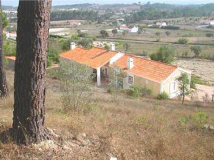
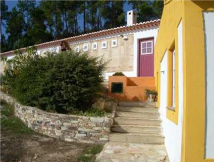
With the aim of validating this type of constrution in terms of the needed requirments to comply the portuguese thermal code, an evaluation of a raw earth building, already constructed, in the portuguese South region of Alentejo, was done. Since this building was construted before the new thermal codes were published, it doesn’t conforms all of their requirments, partiularly in terms of the flat thermal bridges and energy consumptions. However, some simple construction sytems could be implemented so that the building can comply with the new codes.
Simulations with energy plus program have also been done, with the aim of compare inside comfort variable PMV of different construction solutions. A set of conclusions have been developed in terms of construction systems and natural materials that can help raw earth buildings to comply with the new thermal codes.
|
|
|
A free-running intermediate space between the interior and the exterior may reduce infiltration heat losses during winter, allow pre-heating of the supply air to the adjacent space and improve the effective U-value of the external envelope. Typical free-running spaces are entrance halls, conservatories or glazed balconies. The latter two should be located in the southern side and with advantageous window areas to allow indirect gain to adjacent spaces during winter. Shading devices prevent radiation from entering. Openings allow dissipation of heat during the hot periods.
The thermal storage capacity of materials can be used to reduce the peaks of temperature in buildings. Temperature swings will also be reduced in strong inertia buildings.
During summer, thermal mass can be used to lower the upper daytime temperature, thereby reducing the need for cooling. The thermal mass is pre-cooled with night time ventilation, when outdoor temperatures are low, and allow heat dissipation the following day when indoor temperatures are high. Equally, in winter, thermal mass can absorb heat during the day for release into the space at night. This can potentially reduce heating demand. It will need a longer warming — up period, as the thermal mass has to warm up first. For this reason it is appropriate for buildings with permanent occupation and in particular with night occupancy. Offices and spaces that require a quick response to the environmental conditions may require a lower storage capacity.
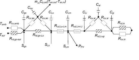
The equations developed for each configuration are very similar. Therefore, they are presented here only for configuration C. The thermal network associated with this configuration is shown in Fig.
2.
![]()
![]()

 ] Convection
The energy balance equations performed in the middle of the outer glazing layer (go), outer air cavity (ao), PV laminate outer glass layer (Lo), PV+EVA layer (Lm), PV laminate inner glass layer (Li), inner air cavity (oi) and inner glazing layer (gi) are written as follows:
4 4 dT
![]()
 |
|
Sgo — hcv, cmb To — Tamb ) — ™go, o (Tgo — Tsur ) — hcv, ao (Tgo — Too ) — hrd, go-Lo (Tgo — TLo ) = PgotgoCv, go
![]()
![]() S — p, (TLo — TLm) (TLm ~ TLj) _p f C ^T^
S — p, (TLo — TLm) (TLm ~ TLj) _p f C ^T^
Lm PV r r Lm Lm v, Lm dt
Rcd, Lo-Lm Rcd, Lm-Li d
(T — T ) dT
TLm — Li — hrd, Li — ATLi — Tgi) — hcv, ai(TLi — Tai) _ pjtT^—Lr
Rcd rm-n dt
In Equations (1) to (7), Sj represents the amount of solar radiation absorbed by layer j, ejo and j are the outdoor and indoor surface emissivity for layer j, Tamb and Tin are the ambient and indoor environment temperatures, Tj is the temperature of layer j, a is the Stefan-Boltzmann constant, Cp, ao is the specific heat at constant pressure of the air in the outer air cavity, W and H are the window width and height, Rcdj-k and hrdJ_k are the conductive thermal resistance and radiative heat transfer coefficient between layers j and k, and pj, tj and CvJ- represent the density, thickness and specific heat at constant volume of the material of layer j, respectively. hcv, in is the indoor heat transfer coefficient calculated with the relation of Curcija and Goss [6], while hcv, amb represents the outdoor heat transfer coefficient obtained with the correlation of Cole and Sturrock [7]. The outer and inner air cavities convective heat transfer coefficients, hcv, ao and hcvai,,are estimated with the relations developed by Wright [8] for non-ventilated vertical air cavities. For the naturally vented cavity, the outer and inner convective heat transfer coefficients, mass flow rate (mao) and air inlet (Taoin) and
outlet temperatures (Taoout) are determined with the correlations found in ASHRAE [9]. The surroundings temperature, Tsur, is a function of the sky temperature, Tsky, and the ground temperature, Tgnd, and is given as
Tur =F( + FgndTAgnd ) (8)
In Equation (8), Fsky and Fgnd are the view factors between the window and the sky, and the window and the ground, respectively, and correspond to 0.5 for vertical surfaces. PPV in Equation
(4) is the power produced by the PV cells at maximum power point per laminate unit area and is calculated as a function of irradiance and cells temperature with the relation found in Poissant et al. [10]. The cells were assumed to be crystalline silicon and the rated peak power of the PV assembly in the 1.44m2 laminate was set to 165W. The total irradiance striking the PV cells and the solar radiation absorbed in each layer were determined by ray-tracing technique by taking into account incidence angle effects and multiple reflections.
Calculations have shown that the PV-window is thermally competitive to the nowadays low energy windows and equally fulfills the requirements within the Danish Building Regulation. Data for the developed PV-window is listed in table 1.
|
Table 1. Thermal data for the PV-windows illustrated in figure 1.
|
Furthermore the PV-window supply the building with electricity and reducers its need for primary energy. Electrical tests have shown that the PV-window is equally competitive to standard PV- panels. The only difference is the inclination of the profile and hence the electrical output.
Test at the Danish Building Research Institute has also shown, depending on the design and layout of the PV-pane, cf. figure 1, that the PV-window can supply daylight and electricity to buildings to fulfill different requirements in different areas in the building.
Students from Aarhus School of Architecture have in a workshop investigated how the developed PV-window can be used to create transparent building components which offer multiple functions apart from transparency and production of electricity. The architect found that the PV-window offers these multiple functions. Depending on the laying up, sizing and carving of the PV-cells the PV-window can offer a high production of electricity, income of daylight, solar shading and interesting reflections. The PV-pane also accentuates the changeability and dynamics within the many characters of daylight. The use of silicon wafers in building design has a cogent and technical expression and it communicate a global friendly/responsible production of electricity.
3. Conclusion
The project group is developing a low-cost PV-window with focus on optimizing the composition of the PV-pane and hence simplifying the production method. These factors can reduce the price of the PV-window with up till 20 % or more compared to similar products.
The PV-pane is built up as a 3-layer construction with gas filling and a TPS spacer profile. With a U-value of 1.2 W/m2K, the PV-window fulfills the Danish Building Regulation and is thermally competitive to the nowadays low energy windows.
As an additional choice the PV-window can be designed with screen printing, variations in the design of the PV-pane, e. g. the size of the silicon wafers and carving of patterns within the PV- cells. This will affect the price of the PV-window.
Summed up this makes the product very attractive for building owners and architects to use in building designs for both new and retrofit buildings in comparison to other renewable energy systems which often tend to deface the building from an architecturally point of view. The PV — window addresses the field of making energy right buildings, using the energy falling on the buildings to supply itself in a fully integrated an aesthetical way and not as an ad on to a building.
It helps reducing the need for primary energy, gives the building a clearly environmentally green profile and at the same time it fully fulfills the requirements within the Danish Building Regulation.
The development of this product has not been completed and will continue.
|
The above study focuses on the analysis of fenestration shading devices and techniques which are developed previously [1], so as to reduce unwanted solar heat gains in the summer, without conflicting with beneficial ones in winter, as solar gains play opposite roles for heating and cooling in the climate of Cyprus. In the study, emphasis is given on occupancy intervention on manually operated shading devices.
For the study, characteristics of windows and shading devices are specified in terms of geometry and physical dimensions profiles, in various simulations. The intention is to describe synthetically how the quality level of the internal environment is affected in response to hypothetical occupant shutter use patterns. These accommodate possibilities of potential conflicts of the double role of solar gains and destructive interference with the effective performance of the “Zero Energy House”.
Tables 1 and 2, sum up the attempt to systematize various possible shading operations by occupants. It illustrates the correlation between solar heat gains or losses resulting from such operations, for the two seasons, and the thermal performance of the “Zero Energy House”. This is done in order to conclude optimum shading design strategies for maintaining comfort conditions in the building considering the operational aspects of shading techniques.
From the results it is evident that the occupants’ interference and misuse of the manually operated window shutters could be counter-effective and might annul the optimized fenestration design. The uncertainties associated with the shading variable and occupant behaviour can be large in occupied buildings. This occurs, where solar gains is a significant part of the design in achieving indoor comfort conditions without the need of mechanical energy, as in the case of the “Zero Energy House”.
The results explicitly indicate that the counter — effect of misused south window shutters could be of vital importance for the maintenance of internal thermal comfort level in winter.
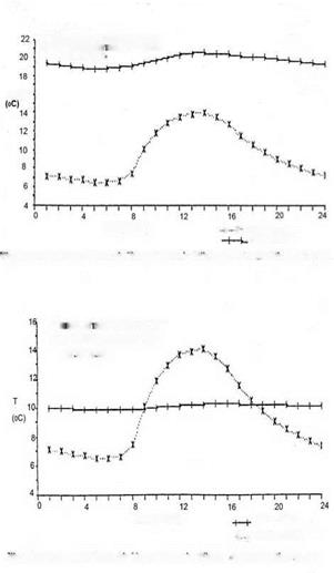
Tables land 2 and graphs 1-4, show temperatures of ambient outdoor and indoor air. Table 1, 1.0 portrays optimised design for winter, in which all shutters are open. It illustrates that the ambient outdoor air temperature varies from 6.5 to 14.0 degrees Celsius, the swing in the inside temperature remains within the comfort zone, from 18.6 to 20.6 degrees only.
The other tables and graphs indicate a drop of indoor temperature ranging from 0.1 to 10.5 degrees Celsius, depending on the extent and orientation of window shutters left shut during the winter day. If all window shutters are left shut, the internal temperature drops below outdoor, by 0.1 to 4.0 degrees. The largest drop occurs mainly between 09.00 to 18.00 hours (table 1, 1.4). These results point out the reliance of the “Zero Energy House” on solar gains.
 /
/
T SIMULATION FOR COLD DAY
ALL FENESTRAT ON UNSHADED
D7.00-19.00
T 16
![]() ! * Outdoor AIR T
! * Outdoor AIR T
Indoor AIR T
rig.!. Indoor and Outdoor Air temperature in >>inter. All fenestration unshaded
T S MULAT ON FOR COLD DAY
ALL FENESTRATION SHADED
D7 00-19 00
![]() TIME (Hours)
TIME (Hours)
X I. Outdoor AIR T
rig.2. Indoor and Outdoor Air Iemperature in Winter. All fenestration shaded
Furthermore the small extent of deviation of temperature, incurring when shutters are left shut on the house elevations other than south, confirm the validity of the optimisation of fenestration distribution and orientation on the “Zero Energy House.”
Table 2, 1.4 and Fig. 4 illustrate the optimised design strategy for summer, with all shading shutters closed, when the outside temperature reaches a maximum of 35.0 degrees Celsius whilst the inside reaches only 25.5 degrees.
Examining the results of the counter-effective human intervention on the manually operated window shutter on the “all-shut” optimised shading profile for summer (Table 2, 1.4), it is noted that this poses no significant conflict on solar control. Comparing the free thermal behaviour of the building under the optimised summer strategy (Table 2, 1.4, Fig.4. “All Fenestration Shaded”), with the less than optimised (Tables 2, 1.3-1.0, Fig.3). The rise 0.4 to 1.0 degrees Celsius of internal temperature indicated for some configurations presents no serious problem. Even when all window shutters remain open during summer day the internal temperature does not deviate from the comfort zone. Over the complete period of investigation the deviation did not exceed 1.00 degree Celsius, indicating at least for the shading variable, the efficient performance of the fixed shading devices of overhangs and vertical extended walls on the southern orientations for the summer season. For both seasons, the results also emphasize the significant role of the optimisation of:
(I) Fenestration distribution and orientation
(II) Permanent shading overhangs and vertical extended walls
On the thermal performance of the “Zero Energy House”. The sun spends very little time during the summer in front of the major fenestration area which faces south; its south passage is at high altitudes, so window design optimization of shading overhangs in conjunction with extended walls, allow effective shielding from direct radiation.
The above observations show that although window shutters contribute to limiting thermal gains in the summer, by reducing indoor temperature up to 1.3 degrees Celsius (table2, 1.4 and 1.0), their negative effects of misusing them in winter defeat the optimized performance of the “Zero Energy House” to the extent of dropping indoor temperature below outdoor during winter (Table1, 1.4).
The results also indicate that the combined effect of the optimum design of fenestration orientation and permanent shading devices provide sufficient sun control without the need of the manually operated shutters and its possible counter-effects.
Even so, if design fenestration aspects such as orientation, size, distribution, and sun control devices, differ to those developed for the “Zero Energy House” the application of shutters for shading could be the only solution. For example, the fixed overhangs do not work for window facing east or west, since the sun is low in the sky in the morning and afternoon. In such cases the introduction of automatic controls is imperative in order to eliminate the negative effects of the manually operated shutters misuse presented above.
[1] D. k.Serghides, (1994) Zero Energy for the Cyprus House, the Architectural Association, School of Architecture, London.
[2] Centre for Experimental and Numerical Thermoflow and Department of Mechanical Engineering, University of Pretoria, (1991) “Quick-A thermal design tool and load calculation computer programme, Pretoria, Republic of South Africa.
[3] Mathews E. h., Shuttleworth A. G., and Hanna G. H., (1992) Validation of a design tool for Low Energy Architecture” Proceedings 1992 World Renewable Energy Congress. Pergamon
[4] D. k.Serghides (1988), Prototype Solar House for Cyprus, the Architectural Association, School of Architecture, London.
[5] Gunnurshaug J., Windows as Solar Collectors, SINTEF, Norwegian Institute of Technology, University of Trondheim, Norway
After the detection of the constructive solutions that do not fulfil the minimum requirements, it now becomes critical to identify the minimum changes needed in order to ensure compliance. This is done in Table 5. The solution for complying with the U-value passes through adding some thermal insulation. It is assumed that this cannot be done at the external face of the walls because it
would change their look, so a solution of internal insulation is considered. Then, to solve the problem of the solar factor, the most internal layer of the walls is changed from gypsum to a brick wall (the insulation thus becomes locked between the stone and the brick). Since the requirement for medium or high thermal inertia is g<0.56 the requirement becomes fulfilled.
Once the minimum requirements have been met, the next step is to verify if the requirements of heating, cooling and DHW needs are met. The results for the several apartments are shown in Table 6. They show that, even if the direct minimum requirements for the envelope are now verified, this is not enough to fulfil the energy requirements. Although all apartments comply with the cooling needs criteria, only one complies with the heating needs criteria. The requirements for the domestic hot water (final energy) are met in the limit (note that at this stage no solar collectors were considered yet). In what regards primary energy, the criteria are satisfied in all apartments except number 5 and 6. Regarding the energy class, at this point it can only be given to the apartment number 4, which is the only that fulfils simultaneously all the requirements.
|
Table 5: Changes from the base-case to ensure the verification of the minimum requirements
|
|
Table 6: Energy indexes after the upgrade to fulfil the minimum requirements
N. C. = Not compliant |
In the systematic model of the Delft’s industrial design engineering process four phases in the product creation can be discerned: analysis, synthesis, embodiment design, and optimization [1]. Each phase marks a different stage of the development of a product design. The end of each phase can be seen as a decision point in which the work done is evaluated and decisions are made for the next phase. Figure 1 shows the Delft’s model for systematic product development and indicates the activities and results per phase.
In the analysis phase the starting point is a design goal or assignment. Information is gathered about all relevant aspects related to the design goal, such as function of the product, market, target group, technology. Results of this phase are a set of design criteria. In the synthesis phase product concepts are generated on the basis of the design criteria. Concepts are worked out up to a level where they can be evaluated on their feasibility in terms of technology, user aspects, production etc. After evaluation, one concept or a combination of concepts is selected for further development. In the embodiment design phase the selected concept is elaborated up to working prototypes. These prototypes are tested and consequently optimised, in the final phase. Finally, the details of the product are worked out up to the level of a production ready product design and a marketing plan is set up as well.
design criteria
![]()
concept design
product design
market introduction
Fig. 1. Phase model of the product design process, translated from [1].
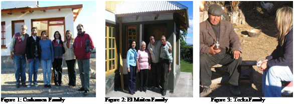 |
Participative Research-Action is used, not only to know the reality but to modify it, strengthen the leadership of the actors involved and rescue the value of popular knowledge and skills as means of change. The experience is supported by the strong intervention of the users in order: a) to develop a house which responds to the real necessities and/or environmental, technological or functional conditioning factors; b) to achieve a sustained process of settling and revaluation of their medium. The work integrates the Farming and Husbandry Social Program for contact and actions with the peasant families (Figures 1, 2, 3). Some belong to the Tehuelche race; they raise yard animals — sheep — and live on subsistence agriculture. Their houses were of adobe and bahareque (panel made of cane and mud) masonry and earth roofs covered by zinc sheet metal; they were characterized by their antiquity, their high degree of decay, precariousness and collapse possibilities.
• Construction modality: it was done by assisted self-construction and mutual aid.
• Walls, Roof and Floor: Materials and manual labour from the site and some industrialized ones were used. Local constructive techniques were reformulated. a) Wall: Solid brick masonry of soil-cement: exterior of 0,30 m of interior thickness of 0,15 m; b) Ceiling: Matched wood ceiling with water repellent insulation — nylon 200 microns — and thermal-volcanic sand and earth of 0,12 m of thickness; Cover of zinc sheet metal on wood structure and thermal insulation — glass wool-; c) Floor: Flagstone on sub-floor of poor H° 0,12 m thickness.
• Energetic and Environmental Conditioning Systems:
A) Solar systems for (Figure 6):
— Passive heating: Solar gain is direct by means of: — Double-glazed windows;-greenhouse; —
Accumulator-collector walls (Modified Trombre-Michel Type) to the North; — accumulator — collector on the roof.
— Storing: Most heat accumulation is done in the exterior and interior walls of the soil-cement.
The great thermal inertia of the facade and its high energetic conservation softens the daily variations of temperature in order to keep heat. It is also done by means of Modified Trombe-Michel Type accumulator-collector walls and roof accumulator-collector.
— Cooking: a solar oven which opens and closes from the interior; — a solar mobile kitchen out of
the house with parabolic concentrator and system with manual solar orientation have been installed.
— Drying of: — clothes; — fruits and vegetables drying
— Hot water: the system possesses a commercial collector of 4 m2, with water accumulator in an
isolated tank which supplies the bathroom, kitchen and laundry artifacts.
— Greenhouse: it is north and west oriented and allows the production of fruits and vegetables
and possesses a polycarbonate cover and double-glazed windows (Figure 7).
— Cooling: It is achieved by means of a “chimney” effect in bedrooms, kitchen-sitting room,
gallery, bathroom and greenhouse.
B) Electric Power: it is obtained by means of a wind-powered generator of 600 w.
C) Heating and Warming of Conventional Water: a high performance Russian-type heater was installed which also complements the system of solar heating of water.
|
|
|
Figure 5: Context-Solar architectural prototype. Figure 6: Walls, roof, chimney. Figure 7: Greenhouse. 4.2. House 2: Buenos Aires Chico, El Maiten. • Geographic location: Latitude: 42°03’.157, Longitude: 71°10’.112, Height: 734,30m above sea level. |
• Technical Data Card: — Project date: 1st of November of 2005; — Construction State: Concluded Work, December 2006.
• Architectural Response: The prototype corresponds to a two-bedroomed unifamiliar house. Its covered surface is 88 m2 plus 8 m2 of greenhouse (total = 96 m2). The architectural parti is synthesized on one floor with the bedrooms and the greenhouse to the North — to achieve greater reception and collection of solar radiation — and with the service premises to the South as “stopper” spaces (Figure 8).
• Construction modality: it was done by assisted self-construction and mutual aid.
• Walls, Roof and Floor: Materials and manual labour from the site and some industrialized ones were used. Local constructive techniques were reformulated. a) Wall: Solid brick masonry of soil-cement: exterior of 0,30 m thickness, interior of 0,15 m; b) Ceiling: Matched wood ceiling with thermal and water repellent insulation (glass wool) and thermal-volcanic sand and earth of 0,12 m of thickness; Cover of zinc sheet metal on wood structure; c) Floor: Flagstone on subfloor of poor H° 0,12 m thickness..
• Energetic and Environmental Conditioning Systems:
A) Solar systems for (Figure 9):
— Passive heating: Solar gain is direct by means of: —
— Heat-sealed double-glazed windows and greenhouse;
— Accumulator-collector walls (Modified Trombre-Michel Type) to the North.
— Storing: Most heat accumulation is done in the exterior and interior walls of the soil — cement. The great thermal inertia of the faqade and its high energetic conservation softens the daily variations of temperature in order to keep heat. It is also done by means of Modified Trombre-Michel Type accumulator collector walls.
— Cooking: a mobile solar kitchen has been incorporated outside the house with a parabolic concentrator and a system with manual solar orientation.
— Hot water: the system of sanitary water system possesses a commercial collector of 4 m2, with a water accumulator in an isolated tank which supplies the bathroom, kitchen and laundry artifacts.
— Greenhouse: it is north and west oriented and allows the production of fruits and vegetables; it possesses a polycarbonate cover and double-glazed windows (Figure 10).
— Cooling: it is achieved by means of a “chimney” effect in the accumulator-collector walls and the greenhouse.
B) Electric Power: the connection is to a local electric system.
C) Conventional Heating and Cooking: a high performance sheet metal oven was installed — “Nuque Oven”- for cooking, heating of water — which supports the solar warming system of water — and heating — with hot air distribution system.
D) Conventional heating of water: the system counts on a highly efficient tank-type water heater which complements the system of solar heating of water.
|
Figure 8: Context-Solar architectural prototype. Figure 9: Solar systems. Figure 10: Greenhouse. |
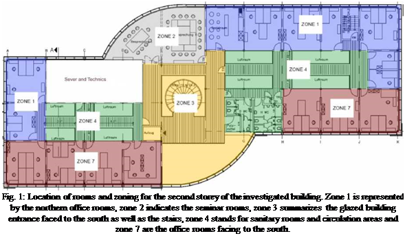 |
The investigated building was planned as a three story office building according to passive house standard with a net floor area of 2155 m2. The building was planned for a location in Germany and consists mainly of office and seminar rooms. In addition, one room was reserved for the server facilities. Fig. 1 illustrates the location and size of the different rooms for the second storey of the building. Additionally, the chosen thermal zoning used within the simulation model is indicated. Both room types and zoning are similar for the other two storeys and are merged to single zones extended over the three storeys. Only for the office rooms facing south single zones for every storey have been used.
The server room considered in the concept represents a special zone within the building, which needs to be investigated independent from the other zones. The server room is located at the northern part of the building, having negligible solar gains. However, a relatively large internal load was assumed for the IT facilities. During working hours (Monday to Friday, 8 am-6 pm), a constant heat input of 15 kW was considered. Outside of working hours, the heat input was assumed to be 7.5 kW. In order to protect the computer devices, maximal temperatures of 23°C are required, which can only be guaranteed by an active cooling system.
All the dwellings are located in the City of Lisbon in zones close to the Tejo River with scattered vegetation and with few obstructions (buildings or constructions). The set of monitored fractions was composed of 11 residences (located in the penthouse, intermediate and one with external floor), 21 compartments composed of living room and bedroom type environments.
The different solar exposures of the various adopted compartments represents the main orientations. These are 10 compartments with the main glassed facade practically to the south (South, SSE, and SSW), 4 to the west (WNW), 4 to the east (ENE) and 3 to the north (North and NNE). The majority of the environments selected present only one face in contact with the exterior (16 compartments) encompassing the principal solar dispositions.
|
Facade(s) Exposed Orientation |
Dwelling |
Compartment |
Location in Building |
FF (Form Factor) |
Glazing Facade(s) Orientation |
Glazing Area/ Facade Area in Corresponding Exposition (%) |
Total Glazing Area/ Floor Area (%) |
Exterior Shading |
Interior Shading |
Cooling System (air conditioning) |
Ffeating System |
|
|
South |
South +East |
H1 |
living room |
Intermediate |
0.29 |
South, ssw, East |
95% South, 4U% East, 97%SSW |
54% |
horizontal shading (>____ |
screen |
Yes |
Yes |
|
SSE |
H 2 |
living room |
016 |
SSE |
85% |
34% |
horizontal shading+vertical awnings |
— |
||||
|
bedroom |
0.34 |
77% |
69% |
black out |
No |
|||||||
|
H 3 |
living room |
Ext. Floor |
0719 |
83% |
23% |
— |
||||||
|
H4 |
living room |
Penthouse |
0.48 |
80% |
20% |
No |
||||||
|
SSE+WSW |
H 4 |
bedroom |
0.81 |
91% SSE |
49% |
black out |
||||||
|
SSW |
H9 |
bedroom |
0.54 |
SSW |
81% |
32% |
horizontal shading (<) + blinds |
— |
||||
|
H11 |
bedroom |
Intermediate |
0.15 |
81% |
32% |
No |
||||||
|
SSW+WNW |
H 9 |
living room |
Ffenthouse |
0.59 |
40% SSW |
16% |
Yes |
|||||
|
HU |
living room |
Intermediate |
0.21 |
16% |
No |
|||||||
|
Wesi |
WNW |
H 7 |
living room |
0.16 |
WNW |
81% |
35% |
|||||
|
bedroom |
0.15 |
81% |
32% |
|||||||||
|
H 8 |
living room |
Penthouse |
0.55 |
36% |
15% |
No |
||||||
|
bedroom |
0.54 |
81% |
32% |
|||||||||
|
East |
ENE |
H 5 |
living room |
Intermediate |
0.15 |
ENE |
84% |
34% |
horizontal shading |
Yes |
||
|
bedroom! |
0.20 |
90% |
46% |
black out |
||||||||
|
bedroom 2 |
0.34 |
77% |
68% |
|||||||||
|
H6 |
living room |
0.10 |
82% |
22% |
— |
Yes’ |
||||||
|
North |
NorthNNE |
H1 |
bedroom |
0.21 |
North |
34%N |
18% |
horiz Shad. (< < |
wood door |
No |
||
|
Ш0 |
living room |
0.16 |
NNE |
81% |
33% |
horizontal shading (<) + blinds |
— |
|||||
|
NNE+ESE |
H10 |
bedroom |
0.29 |
NNE |
81% NNE |
32% |
Navitejo Building Ffertejo Building Alcantara-Rio Building
Fig. 5. Features of flats and compartments selected to study
The majority of the compartments (17) present glazing areas greater than 75% of the corresponding exposed face area (face in which the glass is inserted), in some cases this relation is close to 90%. In terms of floor area the compartment set presents glazing areas of between 15% and approximately 70%, in the majority of these relationships is of 25%-35%. The form factor (FF) varies in the selected sample between 0.1 and 0.5 (16 compartments).
All the fractions present transparent double glass with metal frames, only a fraction of Navitejo building had wood frame. In relation to the exterior shading systems the sample presents systems of the following types: horizontal shading (all buildings), blinds (Alcantara-Rio) and vertical awnings (Pertejo). The wall in contact with the exterior in the Navitejo and Pertejo Building fractions are composed of simple walls with exterior insulation. The thickness of the insulation of the exterior walls and roof are: 30mm in Navitejo, 40mm in Pertejo and 20mm-30mm in Alcantara-Rio.
2. Monitoring
A more detailed appreciation of the buildings were undertaken with the architecture projects (provided by the Studios and respective responsible architects), subsequently the monitoring was implemented during the months corresponding with the summer 2007 and the winter 2007-2008. Dwelling units of the same typology and similar layouts were selected (whenever possible) for the measurements in each of the adopted buildings. As mentioned in the previous section, it was possible to monitor similar apartments with different solar dispositions in different locations of the same building.
During the monitoring temperature and relative humidity sensors were installed (Mini data logger Testostor-175 provided for the study by INETI, normally in the living room and bedroom environments of the residential units selected. The monitoring took place in periods of approximately 15 days. The Data Loggers were positioned so that they would be as centralized as possible in relation to the respective environments being evaluated while not interfering with the resident’s activities. The occupation and utilization pattern of each residential unit was also recorded during the measurements, this information was of relative importance for the interpretation and analysis of the recorded data.
The observations of the external conditions: temperature, relative humidity, wind velocity, wind direction and global horizontal radiation were obtained from the INETI Meteorological Station installed in the Solar XXI Building. In this way it became possible to assume the same external conditions for the all housing units with the data from the Meteorological Station INETI, and then obtaining a data and information set that made possible the observation and verification of the thermal performance and comfort levels in the various monitored fractions in summer and winter situations.