Как выбрать гостиницу для кошек
14 декабря, 2021
Another weak spot that the analysis of the questionnaires and the interviews revealed is the positioning of the blind control switches within the offices. As previously mentioned in Subsection 4.1., four blind control switches are installed in every office. In some cases, the switches can easily be reached by the office occupants. In other cases, the workplaces are located at considerable distances from the switches: Occupants have to leave their workplace to operate the blinds. The situation is worst in offices occupied by two persons: In such offices, one person is typically seated next to the switches, but the other occupant always has to ask his colleague to operate the blinds for him. Even though this ensures a minimum of communication between the office workers, the constant asking for blind position modification can become a source of stress and distraction.
Possible ways to resolve this problem would be the installation of additional blind control switches in offices with two occupants and the shifting of workplaces towards the switches in offices occupied by only one person. However, this might not be easily feasible in many cases. The specific situation at the LESO-SEB offers a much more elegant way to deal with the blind control problem. All lighting, heating and blind devices are actually interconnected via an EIB-system (EIB = European Installation Bus). Most switches and sensors installed within the building are also connected to the EIB. It is also possible to connect computers to the EIB. Figure 4(left) shows a schematic overview of the installation. During another project recently carried out at laboratory, the possibility of using a portable server device (“MyHomeBox”) for blind and luminaire control via the EIB-system was studied [11]. It was demonstrated that it would be easily possible to give LESO-SEB occupants the possibility to control their luminaires and blinds via a flash application installed on their PC (see Figure 4(right) ) that communicates with the portable server device. Installing this application on all occupants’ PCs is a very interesting option for effective work comfort enhancement within the ADS-equipped LESO-SEB offices.
|
Figure 4: Left: Schematic overview of the installations within the LESO-SEB: All installations are interconnected via an EIB bus system. The installations can be controlled via computers connected to the bus system. Right: Flash application developed at our laboratory that allows lighting and blind control via the EIB from occupants’ PCs. |
YuXiang Chen*, A. K. Athienitis, K. E. Galal
Solar Buildings Research Network www. solarbuildings. ca
Department of Building, Civil and Environmental Engineering, Concordia University, Montreal, Quebec,
Canada
Corresponding Author: yuxia ch@alcor. concordia. ca
This paper describes the thermal performance assessment of a demonstration solar house with a building-integrated photovoltaic-thermal system (BIPV/T), passive solar design and a ventilated concrete slab (VCS) for solar heat storage, and the modelling of the BIPV/T and VCS. The house was designed to achieve close to net-zero annual energy consumption. Several innovative solar technologies are adopted in this house to meet the design goal. BIPV/T system collects thermal energy from the photovoltaic panels (PV) and cools down PV at the same time. The VCS system stores part of the collected thermal energy in the heating season. Large south facing triple glazed windows and distributed thermal mass are employed for passive solar spacing heating. An integrated supervisory control system is used to optimize the performance of conventional mechanical system and solar energy systems. The house was completed in 2007 and preliminary results are presented. Thermal network simulation models using for the BIPV/T and VCS are presented. It is validated with the measured data and shown to be satisfactory for design and control of the system.
1. Introduction
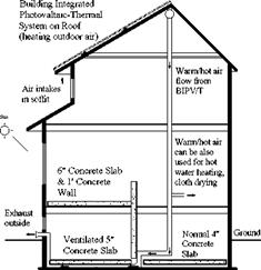
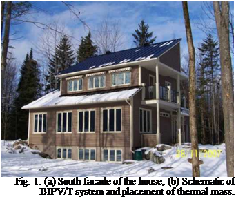
The Canadian Solar Buildings Research Network is conducting a major research program focused on the design and demonstration of net-zero energy solar buildings under Canadian climatic conditions. The Canada Mortgage and Housing Corporation (CMHC) launched a demonstration initiative, EQuilibrium Housing in 2006. As one of the twelve selected demonstration houses across Canada, the solar house considered in this paper was designed and built in 2007 by a prefabricated home manufacturer in collaboration with the Solar Buildings Research Network. This energy efficient solar house is designed to achieve annually close to net-zero energy consumption through optimal integration of conventional heating technologies such as geothermal heat pump, BIPV/T roof system, passive solar design and active thermal storage (Fig. 1). The house is located near Eastman, Quebec, Canada. Table 1 shows the monthly average dry bulb temperatures of Eastman. The house is designed to accommodate a four-person family. The total floor area is about 140 m2 excluding the 90 m2 basement floor area. A healthy and comfortable home that is energy efficient, and yet affordable, and easy to be constructed is the overall goal of the design.
|
Table 1. Monthly average dry bulb temperature (°C).
|
 |
 |
To achieve the net-zero-energy goal, reduction of the energy consumption for space heating and domestic hot water (DHW) heating is critical. Passive solar design can greatly reduce the space heating fuel consumption [1]. BIPV/T can harvest considerable amount of heat from solar irradiance while producing more electricity due to cooling of the photovoltaic roof. This collected heat can be used for space and DHW heating. In order to maximize the potential utilization of the collected heat from the BIPV/T and the heat transmitted through south-facing windows, thermal mass is needed to store the excess part of this energy and release it later in an appropriate manner [2]. In the case of this house, actively and passively charged concrete slabs and walls are adopted to serve this purpose. Distributed thermal storage integrated in a building has been shown to be efficient and effective in improving the thermal performance of buildings [3, 4]. It can reduce the thermal fluctuation and load, and also shift the peak load. Concrete is a common and effective building material used as thermal mass [5]. Concrete slab, in a distributed form, has its advantages in functioning as thermal storage and structure. Athienitis et al. [2, 6] conducted experiments and simulations to study the thermal behaviour of both passively and actively charged concrete slab in passive solar buildings. Several kinds of VCS have also been studied by several researchers [7, 8].
(a) (b)
In the first experience (Rebibbia jail, Rome, 2002) 30 prisoners attended the training course while 18 of them ended it. That has to be considered a good result compared to the average level of participation in professional training courses, that is around 10%.
The new ongoing trainings in Rome, Turin, and Laureana di Borrello (Reggio Calabria) are based on smaller classes with a higher commitment: around 80% of attendants partecipation recorded in the first theoretical phase.
A specific training module has been developed to underline the social value of the programme, and a technical and psychological commission selected the people to be involved in the courses, evaluating their attitude to technologies and new jobs.
The course is preceded by motivational interviews while the motivation degree is monitored during the training through moments of group evaluation.
The assessment is made through the submission of questionnaires (self empowerment, technical skills) before, in the middle and at the end of the training.
The main aims for social supporting are:
1. To contribute to the successful installation of the solar plant by an internal awareness and "ownership" integrating technical training with a motivational and psycho-social path.
2. To promote the acquisition of new abilities in order to look at the educational training as an experience of growth and self awareness towards environment and new opportunities regarding the external society.
3. To acquire the ability to work in team and, consequently, to promote social skills on job training and team building.
The most challenging difficulty to be overcame in the practical job was the integration among different approaches and cultures. On the other hand, the positive interdependence among different abilities, and the introduction and consolidation of a pluralistic culture and competencies in practical activities, developed a proper use of the group as an instrument of empowerment.
 |
Millennium Partners development on BPCA Site 2A, The Millennium Tower Residences, also utilizes the SunPower A-300 solar cell but in a custom laminate as part of a facade wall at the mechanical bulkhead. The developers are pursuing all available funding. The goal of the developer is to achieve a USGBC LEED® Gold Certification.
The development and design team set a goal of making the system the most efficient to install as to purposely avoid trade disputes. A well thought out design allowed for 14 pre-glazed wall units to be
raised in a single day by crane to the buildings bulkhead. Ornamental Ironworkers installed the system and Electricians wired it up later. No on site trade disputes occurred, making this perhaps the most efficient installation to date in New York City. However, under pressure from new internal guidelines, UL would not field list the project and since the installation was complete, there was great concern as to whether this project would ever be accepted by the local authority having jurisdiction. Eventually another Nationally Recognized testing Laboratory agreed to field list the system and therefore another barrier for BIPV was overcome with the ability to have multiple laboratories evaluate BIPV systems in the field. This created new options for furthering BIPV implementation in New York City and the rest of the United States.
In order to get the influence of the water supply temperature on the ability of supplying energy, the computational results with the water supply temperature are 20°C, 15°C, 10°C, 50°C, the ambient
 |
 |
temperature is 35°C and the indoor air temperature is 28°C, respectively, are analyzed and discussed.
Fig.9 and Fig.10 represent the floor temperature distribution contrast curve of different medium temperature and the wall temperature distribution contrast curve of different medium temperature, respectively. It can be seen from Fig. 9 and Fig.10 that temperature distribution curves under supply cooling are opposite to the heating. The floor temperature has a minimum value at the embedded pipe; the wall temperature distribution is monotonically increasing.
|
Table 6 The computed result of ability of supplying cooling with different medium temperature
|
The computed results of cooling ability with different medium temperature are listed in Table 5. Table 5 indicates that the water supply temperature has great impact on cooling ability. Combined with Table 3 we can see that, the total thermal flux in summer is lower than in winter because of the total thermal flux depends on the temperature difference between water supply temperature and indoor air temperature.
Form Table 5 we can see that, the energy supply of floor is higher than the wall and the energy supply of floor accounts for 60% of total energy supply of the system whether winter or summer. Above phenomena is determined by the location of the embedded pipe and the thermal conductivity of the materials in the heat transfer area.
3. Conclusions
In the paper, a numerical investigation on the new type radiation energy supplying system is performed. The following conclusions can be made:
1. The capacity of the system is affected by diameter of embedded pipe, location of embedded pipe, water supply temperature. The capacity of the system increased with the increasing of the diameter of embedded pipe, but the cost of the system increased also; the ability of supplying energy of floor was approximately 60% in the total capacity of the system; the increased of the water supply temperature could improve the ability of supplying energy of the system.
2. The practical application of the system shows that the cooling and heating energy need have enveloped energy saving buildings with 40°C heating medium in winter and with 10°C cooling medium in summer. The heat transferred through the floor occupied 60% of the total in summer.
3. The system can prevent condensation on the floor surface in the absence of dehumidification system, because of higher water temperature in summer; the system can prevent surface crack of floor or wall, because of lower water temperature in winter
References
[1] M. W. Liddament, M. Orme, Energy ventilation, Applied Thermal Engineering 18 (1998) 1101-1109.
[2] P. Weitzmann, J. Kragh, P. Roots, Modelling floor heating systems using a validated two-dimensional ground-coupled numerical model, Build Environ 40 (2) (2005) 153-163.
[3] K. Lin, Y. Zhang, X. Xu, Experimental study of under-floor electric heating system with shape — stabilized PCM plates, Energy and Building 37 (3) (2005) 215-220.
[4] K. Lin, Y. Zhang, X. Xu, Modeling and simulation of under-floor electric heating system with shape — stabilized PCM plates, Build Environ 39 (12) (2004) 1427-1434.
[5] A. Laouadi, Development of a radiant heating and cooling model for building energy simulation software, Build Environ 39(4) (2004) 421-31.
[6] O. Bozkir, S. Canbazoglu, Unsteady thermal performance analysis of a room with serial and parallel duct radiant floor heating system using hot airflow, Energy Build 36 (6) (2004): 579-586.
[7] B. W. Olesen, Radiant floor heating in theory and practice, ASHRAE J 44 (7) (2002) 19-26.
[8] Stetiu Corina. Energy and peak power saving potential of radiant cooling systems in US commercial buildings, Energy and Buildings 30 (1999) 127-138.
[9] A. M. Stanley, Chilled ceiling in parallel with dedicated outdoor air systems: addressing the concerns of condensation, capacity, and cost, ASHRAE Transactions 108 (2) (2002) 220-231.
[10] L. C. Christopher, A. M. Stanley, Ceiling radiant cooling panels as a viable distributed parallel sensible cooling technology integrated with dedicated outdoor air systems, ASHRAE Transactions 107 (1)
(2001) 578-585.
The main circular interior space, despite its size, embraces the congregation intimately maintaining the feeling of a Church and providing a panoramic view of the Presbytery. The external walls, clad in a light beige colour sandstone similar to the existing buildings, and the — invisible from the outside — saw-tooth roof structure define the character of the building.
|
Fig.5 Analysis of circular shape |
The SWH had been installed on the rooftop for 14 years. This was an indirect system, which consisted of two flat-plate solar collectors and a hot water storage tank with an inbuilt heat exchanger, as shown in Figure 2. This system configuration represents the majority of domestic SWH systems installed in the Maltese islands.
|
Preliminary inspection of the SWH system identified a number of shortcomings in the layout and operation of the equipment. These were typical defects which were identified in a number of systems during an earlier study of installed SWH systems in Malta [5] . The main defects were as follows:
• The solar collectors were not optimally aligned. Orientation was 32° degrees East of true South;
• The pipe that supplied hot water from the SWH to the washing machine had no insulation;
• The solar tank was showing signs of deterioration and there was evidence of some water leakage;
• The electrical back-up heater of the SWH was left switched on all the time, with its thermostat set at 78 °C. This implied that the water in the solar storage tank was continuously being kept at a high temperature; even when not required, leading to higher heat losses and higher electricity consumption. Moreover, the high setting would reduce the effectiveness of solar energy absorption during the day thus reducing efficiency [6] ;
• The solar system was under-designed as it supplied hot water to 2 bathrooms, a Jacuzzi, the kitchen and a large washing machine. The washing machine alone consumed 130 litres per wash — part of which was invariably hot water.
• It was noted that no routine maintenance was carried out on the solar system (change of sacrificial anode, cleaning of tank, etc.)
Monitoring of salient parameters of the SWH system was also carried out, such as inlet and outlet solar panel temperatures and horizontal solar radiation. The results of these measurements are shown in Figure 3. The outlet panel temperature was higher than the inlet temperature as would be expected. Moreover, the hot water temperature was in phase with the solar radiation levels, which was also to be expected for a well-functioning solar panel. Thermographs of the SWH were also taken and the collectors exhibited higher temperatures in the upper portions of the risers and in the top header [3] .
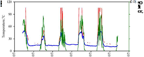 |
Fig. 3. Plot showing panel inlet and outlet temperatures, ambient temperature and solar radiation.
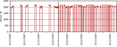 |
A measure to rectify part of the SWH operational issues was the installation of a timer switch of appropriate power rating to control the electrical backup heater. The timer was tested between 19 and 27 December 2007. This timer was set to switch on early morning and late afternoon. Operating the electrical backup heater in the morning was requested as the homeowners were used to washing clothes early morning rather than later in the day. The latter practice would have been preferred, as the water would have absorbed sufficient solar energy rather than being heated by the electrical backup element. The effect of installing a timer to control the electrical backup heater is illustrated in Figure 4, between 19 and 22 December. Thereafter, the homeowners reverted to thermostat control of the electrical booster, since they had guests for the festive season and they were concerned that hot water might be insufficient. When the timer was in control, the average daily electrical consumption of the back-up heater was 11.43 kWh, but when the thermostat was in control, without the timer, the consumption increased to 17.12 kWh/day. Therefore, the introduction of the timer had saved one-third of the electrical consumption of the electrical backup heater, or 12.37% of the total electricity bill of the house over the full monitoring period.
Fig. 4. Effects of timer control on the electrical backup heater in the SWH storage tank.
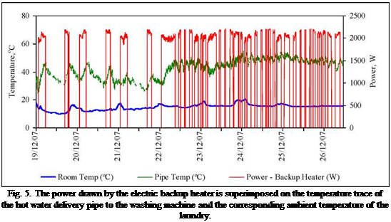
Another test was carried out whereby the surface temperature of the pipe delivering hot water to the washing machine was measured together with the laundry / pantry ambient temperature. Figure 5 shows the results together with the power consumed by the SWH electrical backup heater superimposed. Whenever the electric booster was switched on, it heated the water in the solar storage tank, as well as the water in the hot water delivery pipe to the washing machine, which was over 25 metres long and un-insulated. Given that the temperature gradient between the pipe and the ambient was large, heat losses were inevitable.
 |
Figures 6a and 6b show one end of the solar water storage tank, where the electric backup heater is located. The rectangle sitting centrally on the plastic cover is a highly reflective specifications label. Heat loss in the vicinity of the electrical backup heater is evident as this part of the tank does not usually have insulation. The un-insulated pipe show a high temperature of 41 °C, while the ambient temperature was 17 °C — a source of heat losses as well.
Figs. 6a & 6b. End view of the SWH storage tank showing the cable feeding the electric backup heater housed
under a plastic cover.
Building Science Group, University of Karlsruhe, Englerstr. 7, D-76131 Karlsruhe, Germany
* Corresponding Author, wagner@fbta. uni-karlsruhe. de
The innovative building services concept realized in the Museum Ritter was designed to reduce the energy consumption of air conditioning and lighting significantly. At the same time, the remaining energy demand is covered mainly by renewable energy. The building is intensely monitored for two years within the research program EnOB (energy-optimized buildings) funded by the German Federal Ministry of Economics and Technology (BMWi). Thereby many data points are measured and the reached specific energy consumption values are compared with the planned values. Further, the operation data of the technical installations are measured to find malfunctions and chances to optimize the performance of single components and the whole system. In the following article a description of the building, the energy concept and the monitoring system is given. Furthermore the interpretation and optimization is shown for the example of the absorption chiller.
Keywords: solar cooling, absorption chiller, monitoring
1. Introduction
The energy consumption of museums is very high in comparison to office or residential buildings. The reasons are the requirements for indoor climate and lighting. On the demand side, savings are only possible to a limited amount. Therefore means must be found to cover the demand in a way that preserves the natural resources. In the Museum Ritter several approaches were realized to attain this goal.
2. The Project
The Museum Ritter is located on the outskirts of the small town Waldenbuch next to the chocolate factory Ritter Sport. It houses an art collection of modern geometric-abstract art. In a conscious analogy the layout of the building is based on geometrically clear forms. The floor plan of the 44 x 44 meter construction, which echoes the square, is divided into two wings. Each of the wings is shaped like a trapeze. They are connected with a passage. The larger wing contains the art collection, changing exhibitions, a shop and a cafe. The smaller one contains the visitor center of the Ritter company: The chocolate shop, the chocolate exhibition and the chocolate workshop for children. In addition, 400 square meter office space for the administration of the factory is placed on the second level of this wing.
One salient finding in the three buildings at Blaue Heimat, Rislerstrasse KfW60 and KfW40 was the relative high hot water consumption at 28 kWh/(m2NFAa) (including circulation). This value is 70 % above the target. In addition, Blaue Heimat had 6 kWh/(m2NFAa) of distribution and storage losses due to the central system used. Energy consumption for hot water was much lower in Freyastrasse at
18.4 kWh/(m2NFAa), which was below the target value; part of the reason was the lower number of occupants and the lower circulation losses.
The cogeneration unit in the Blaue Heimat building provides almost all of the heat required. On the average, the cogeneration unit had an efficiency of 89 % and covered 96 % of the heat demand. Thus the possibility of a high CHP fraction as an important part of a net zero energy strategy is shown. Even though the pipes were well insulated (200% compared to the German standard) the storage and distribution losses become a non neglecting part of the delivered heat. The chopping of the CHP unit was suppressed applying an appropriate sizing of the storage.
In Rislerstrasse, the gas-condensing boiler and storage tank had an average efficiency of 85 % in 05/06 and 91 % in 06/07, which were as expected. The solar collectors covered 40 % of hot water demand in Rislerstrasse, which is a quarter of the overall heat demand.
Typical March day is represented by relatively low outdoor air temperatures and moderate solar radiation, so generally there is no need for cooling. Nonetheless, if the direct global radiation is high enough, it can cause overheating of internal living and working spaces. In such cases the overheating can be avoided if shading is properly used. Desired result of automated regulation of solar gains during

early spring would be the prevention of overheating during day-time but at the same time enabling adequate heat gains from solar radiation to sustain internal air temperatures above the external ones during night-time.
Fig. 2. Experiment conducted during two early spring days (9th and 10th of March). The internal conditions in the test cell were regulated according to the set-point indoor air temperature, available global solar radiation and external air temperature. The indoor air temperature profile exhibits the effect of cooling induced by shading the window from solar radiation — evident in the shift between the peaks in external and internal air temperatures as well as in 3K lover day-time and 3 K higher night-time temperatures. The internal conditions were regulated only
by the positioning of the roller blind.
Both days are characterized by very changeable weather, where times of clear and overcast sky frequently exchange. This weather pattern can be distinguished from the “spiked” distribution of measured direct solar radiation. On both days during day-time external air temperatures reached maximum levels just below 14 °C, on the other hand night-time minimal values plunged just below 7 °C. During the first day direct solar radiation reached maximum value of 433 W/m2 at 11:00. In the afternoon much lover values were recorded and the roller blind was mostly open as there was no danger of the test cell overheating. Because available solar radiation was low the roller blind was never
completely closed during the first day. On the second day external air temperatures were almost identical to those on the first day, but the amount of available solar radiation was greater. Maximum value of 706 W/m2 of solar radiation was achieved approximately at the same time as on the previous day. During times of high solar radiation levels on the second day of the experiment the roller blind almost completely covered the window, although times of fully extended roller blind were very brief. During early spring experiment the system was able to regulate internal thermal conditions in the desired way. This means that by positioning the roller blind the interior was kept cool and at the same time enough solar gains were acquired as to heat the interior of the cell during evening and night-time.