Как выбрать гостиницу для кошек
14 декабря, 2021
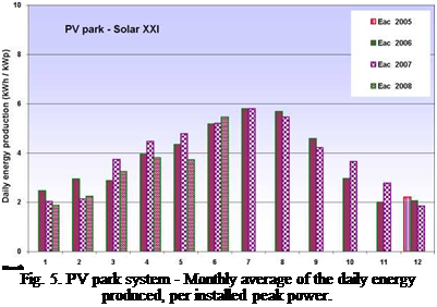
Fig. 5 presents the values of the monthly averages of the daily energy produced in the park, per installed peak power. This system produces more energy in summer periods with a maximum average daily production of 34.8 kWh at July 2006 and July 2007. The production minimum occurred at December 2007 with a daily average production of 11.1 kWh.
At Table 4 we present the yearly irradiation and energy produced by PV Park system. The yearly irradiation measured, in the 15° tilted surface, is about 1 790 kW/m2 each year and the energy production is about 1 400 kWh per kW of peak power installed. The low production in 2006 year, despite the bigger irradiation, is due to an inverter failure during two weeks in the month of May.
|
Table 4. Yearly energy produced by PV park system, per installed peak power
|
This results show that the energy production by installed peak power of the facade system is about
28.6 % lower than for the park system, this is due mainly to the lower incident irradiation on the facade surface.
Systems that use Phase Change Materials (PCM) can be used to store energy. All substances store energy when their temperature changes, but when a phase change occurs in a substance, the energy stored is higher. Furthermore, heat storage and recovery occur isothermally, which makes them ideal for space heating /cooling applications.
3.8 Colour of exterior surfaces
A light colour of surfaces is an effective solution to reduce unwanted solar gains. The quantity of radiation that is absorbed by a surface depends on its colour. Light colours are effective in reducing cooling loads, whereas dark ones are more appropriate to absorb heat in thermal storage.
3. The Portuguese Passivhaus proposal
This section presents a prototype Passivhaus proposal for Portugal. Detailed results from parametric analysis as well as the other partner’s proposals for the UK, Spain, Italy and France are available in the technical guidelines produced in the project. [6]
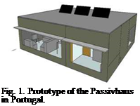 |
The Portuguese Passivhaus proposal is a two-bedroom house which complies with the national building thermal regulation 2006 (RCCTE, DL 80/2006). The prototype avoids imposing a specific layout allowing the architects the freedom of design. The strategies applicable to the Passivehaus proposal were adapted to the Portuguese context, in particular those regarding the cooling season. Special care was taken to adopt commonly-used building practices to avoid an increase of the overall cost and to ease the procurement and its implementation. The current proposal, with a total useful area of 110 m2, takes into account the local climate (case study for Lisbon). It relies initially on passive strategies complemented with simple active systems, if required. Three main aspects are explored in the proposed house: relation with the sun, ventilation for cooling and high thermal mass to control temperature swings.
A typical small 3-storey office with a total floor area of 4200m2 was modelled in the Energy Efficiency Measure module of RETScreen [14] with the TMY weather data used in the TRNSYS simulations. This software is meant for pre-feasibility studies, but it was used in this case to easily compare the building space heating and cooling energy requirements of the different scenarios and avoid the complexity of multi-zone building simulation tools. The building lighting, equipment and appliances load, occupant density, natural air infiltration, ventilation rates and schedules were set to typical values for small office buildings [15]. The windows on all the non south-facing facades
were assumed to be fixed, low-e, triple-glazed and to have an overall U-value and SHGC of 1.57 W/m2oC and 0.27, respectively. The percentage of fenestration was set to 20% on the north wall and 40% on the east and west facades. The other building envelope properties for each city were selected to fulfil the minimum requirements of the Model National Energy Code for buildings (MNECB) [16] with oil selected as the principal heating source for Iqaluit and Yellowknife. The substitution of spandrel panels with multi-glazing BIPV systems was considered to have negligible effect on the lighting load.
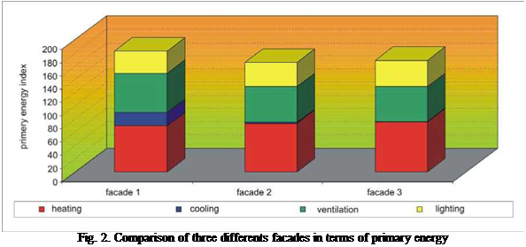 |
A user of the evaluation system can find the stored energy data of any fa? ade system he is interested in by an EXCEL tool. Figure 2 shows an example with the the comparison of three different fa? ade systems in terms of primary energy for heating, cooling, ventilation, and lighting.
By the comparison of different facade systems the energetic advantages and disadvantages of morphological variations of the facades can be found easily. In order to combine the evaluation aspect of primary energy with other aspects, like e. g. embodied energy, in an overalll evaluation, the
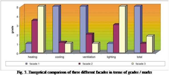
transformation of energetical data into marks can be helpful. Another way of cumulation are life-cycle balances. Figure 3 shows an example for the comparison of three fa? ade systems in terms of grades / marks on a scale from 1 (low grading) and 5 (high grading). The evaluation system offers a special EXCEL tool for calculating the embodied energy, based on tables with specific values for the most common building materials.
The hourly building thermal behaviour was simulated with the soft SIMEDIF for Windows, a code developed at INENCO and widely used in Argentina [3, 4]. SIMEDIF needs the building to be divided into thermal zones, that are represented by an air node with a single temperature, whose temporal evolution is determined by using the building data, materials, location, orientation, connections with other zones and climatic conditions. The zones can be connected to each other and with the outdoors by pre-defined elements, that can store and transfer heat by conduction and convection (radiation is linearized). An energy balance is performed at each node for which the temperature is to be determined. In this global balance equation, the air renewals in the room, inner
 |
heat gains, and heat transfer due to the different elements connecting the room with other zones in the building and with outdoors, are considered. More details can be found in [3].
 |
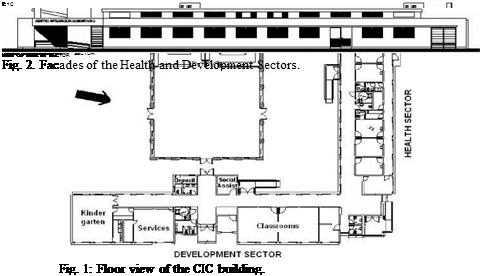
The thermal zones for Development and Health Sectors are shown in Fig. 3. The Health Sector was divided in eight thermal zones (access, South corridor, North corridor, doctors offices 1 to 3, bathrooms, doctors offices 4 and 5, laboratory and meeting room) and the Development Sector in six thermal zones (kindergarten, services, corridor, deposit, social assistant office, and classrooms). The building was simulated under a non occupancy schedule, for typical winter and summer days.
The meteorological data were obtained from Table 1 and the hourly temperature and solar irradiance was automatically calculated by SIMEDIF from mean daily values. The solar absortances were fixed in 0.3 for external wall surfaces (light colour painting) and 0.7 for external roof surfaces (dark red painting).
The BALL light is designed as an affordable lighting solution for households in rural areas of Madagascar. The product price had to be low and the specific needs of the Malagasy users were to be taken into account. An interesting finding was that the future users indicated that the bigger the solar panel, the better the product would be for them. Other people could see better that they use PV solar energy because a it would be more visible with a big solar panel.
The BALL Light is powered via a separate PV panel. The decision to use a separate PV panel was based on the use context. A separate panel would be installed outside on the roof and proper charging of the product’s battery could be ensured. BALL Light is cheaper than other products offered for the same function. It is dimmable and can be used on the table, hanging from the ceiling, as a night-light and as an orientation light outside.
A prototype was made and as a follow up of the project, further detailing takes place in oder to take it into production.
Fig. 6. BALL light on table (left) and PV panel on roof (right)
None of the projects would be satisfying operational without detailed support and optimisation in the beginning over a period of 3 to 6 month. The supervision and adjustment of set points and flow rates has significant impact on the performance and is even for experienced people difficult to foresee.
All of the plants have proven to operate reliably. The Cooling machines achieve the COP detailed in the manufacturers’ specifications during constant operation. Low return temperatures from the cooling tower often allowed a lower flow temperature from the solar plant to be used to drive the cooling machine than that specified by the manufacturers.
The offset between maximum solar radiation and the maximum cooling requirement is approx. 2-3 hrs and can be easily covered using the buffer tank.
The efficiency of conventional flat plate collectors, as used for warm water production is noticeably reduced in this application. Flow temperatures up to 100°C on the primary side of the heat exchanger, result in a lowering of the collector efficiency curve. In large plants it is also important to balance the collector hydraulics.
In the last projects, we used a dramatically improved large area flat plate collector, which in the required temperature range collects approx. 20-30% more solar energy. The economy of the entire concept is thereby much improved. This collector has just passed certification and actually is ahead of not only flat panels, but as well significantly better performing than vacuum tubes at temperatures of 100° C. Practical experiences show we can reach solar gains of app. 750 kWh/m2 in the Arizona project on a mean temperature level for collector operation of 80 to 90°C.
The modifications to the collector include more measures towards reducing the heat loss: a Teflon sheet above the absorber plate reduces top losses, increased insulation in the rear panel and an especially airtight frame also improve performance. These new collectors also offer potential for application in district heating and process heat.
The cooling load can often be entirely covered by the solar plant when we have availability of space for solar panels — particularly on sunny days. The back up is only required on days with little solar radiation. However, the peak electricity demands on the mains supply and distribution network due to cooling requirements don’t generally occur on these days.
Absorptions chillers have proven to be really stable. Not only mishandling though local personal never affected them seriously, I actually found chillers in operation since more than 70 years that are still operating sufficiently.
Diagramm 7 shows average solar gain per day used for cooling (blue column) and
heating (red) in DOC project in Arizona.
TriBeCa Green used New Construction Program funding through NSYERDA PON 593 as well as all available Federal Income Tax credits and Accelerated Depreciation. Located at BPCA Site 19B, it has a PV system on the east, south and western facades of its mechanical bulkhead sized to 27.3 kWp. The system works as a weather shield mounted to the exterior of a structural CMU block wall and utilizes standard UL Listed modules, the SunPower SPR-210 with its high efficiency PV cell, the A-300. The developer for the project, is pursuing USGBC LEED® certification for this project as well.
The architect barely considered trade concerns during design and the development team and the construction manager embraced installations of the PV array by Electricians. This would set a precedent for such installations in the future with the International Brotherhood of Electrical Workers (IBEW) Local 3 of New York City claiming all PV installations if a UL Listed product is used, (Ornamental Ironworkers still have the claim historically for facades dating to the Cast Iron facade period of New York City’s construction history). This installation took extremely long to
complete and was riddled with poor coordination issues. In the end the electrical contractor would state that they would have “little interest in further PV installation work.” Apparently the electrical contractor suffered financially on the project. IBEW Local 3 would still be watching out for any UL Listed PV installations however.
Located at the corner of West 57th Street and 11th Avenue in Manhattan, The Helena took advantage of NYSERDA under PON 716 incentives, the NYS Green Building Tax Credit, Federal Income Tax Credits and Accelerated Depreciation. Developed by The Durst Organization, a green building pioneer, along with Rose Associates, the building features a 14.5 kWp vertical wall PV system at the 39th through 40th floors of the buildings mechanical bulkhead using standard UL listed PV modules from General Electric along with a custom laminated 2.5 kWp entrance canopy.
The Bulkhead system acts as a rain shield and was installed by a composite crew of Sheet Metal Workers, Ornamental Ironworkers and Electricians for wiring. The standardized modules were used in a panelized custom wall system with painted aluminum wall components. The design and planning worked well and the somewhat complicated bulkhead wall system was installed without much delay or concerns raised by trades.
|
Fig. 4. The Helena. |
The BIPV canopy system uses non-listed modules and was installed by Glaziers and wired later by Electricians. Overall this was a smooth installation that went as expected. Special permission from the NYC Bureau of Electrical Control is required for the entrance canopy since, as a custom installation, it will not be delivered to the site with the UL mark. NYC, with all of its codes and requirements, does have the bureaucratic ability to approve such projects when promulgated standards cannot be realized. This BIPV canopy system was the first custom BIPV system Field Listed by Underwriters Laboratory (UL) in New York City setting a president for future BIPV designs. With the possibility for Field Listings, designs could be free of the worry of approval and thus not be forced to use listed equipment which had become automatically claimed by Electricians and past project experience had shown that these installations were the most expensive and delayed. True BIPV had become smart, efficient and less risky.
Influence of the diameter on the energy supply ability was simulated under the indoor air temperature of is 20°C, ambient temperature is 35°C, water supply temperature is 10°C, and the other parameters in summer are the same as those in winter.
 |
 |
Fig.5 and 6 represent that, the larger diameter of the embedded pipe, the lower temperature of the radiant area and the stronger cooling supplying ability; the temperature distribution contrast curves of different embedded pipe diameter are parallel. Area of distance from wall corner is approximately 0.3m was chosen for calculating the total thermal flux of the system; the results are listed in Table4.
Fig. 5 The floor temperature distribution Fig. 6 The wall temperature distribution
|
Diameter of embedded pipe (mm) |
13 |
16 |
19 |
|
Thermal flux of the floor surface (W/m2) |
36.8 |
40.4 |
43.7 |
|
Thermal flux of the wall surface (W/m2) |
35.0 |
38.1 |
42.6 |
|
Total thermal flux (W) |
331.4 |
362.3 |
398.5 |
The computed results of cooling ability of different embedded pipe diameter are given in Table 4.
It is found from Table 4 that, the total thermal flux increased 6.3% and 20.2% under the diameter of embedded pipe of Ф16 and Ф19 comparing with under the diameter of embedded pipe of Ф13.
Meletitiki — Alexandros N. Tombazis and Associates Architects Ltd.
27, Monemvasias st., GR-151 25 Polydroso — Athens, Greece
e-mail: meletitiki@hol. gr
The paper focuses on the presentation of the new Church of the Most Holy Trinity in Fatima, Portugal. The project is a result of an invited architectural competition held in 1997-98. The Church was consecrated on 12 October 2007 in the presence of about 250.000 persons at the Sanctuary of Fatima. The Church can seat just under 9.000 pilgrims. Its main praying area is comprised of a circle of 125m diameter spanned through its centre by two parallel pre-stressed white concrete beams. Its main bioclimatic feature is its roof. Extensive photographic material and drawings will accompany the presentation.
Keywords: church, sustainability, daylighting, bioclimatic design
1. Introduction
 |
In order to erect a Church for 9,000 pilgrims, the Sanctuary of Fatima in Portugal launched a two stage international competition in 1997 between pre-selected architects.
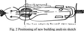 The new building has been set opposite the existing historic Basilica and in front of the Pastoral Centre at the south end of the 500X150m square with easy access for large numbers of visitors. It thus creates a monumental axis which is further accentuated by the circular shape of the new structure.