Как выбрать гостиницу для кошек
14 декабря, 2021
The developed tracking system searches the optimal orientation of a surface, related to the sun incident radiation.
The global performance of the system is described below. The planar surface is composed by a photovoltaic cell which is motorized by 2-orthogonal axis. These two controlled DOF (Degrees Of Freedom) are managed by a PLC (Programmable Logic Controller) according to a search
/programme that compares the electric power produced by the photovoltaic cell in each correspondent orientation. The maximal power value is stored and the correspondent orientations on both motorized axis are stored. This new optimal orientation of the tracking system is then communicated to the industrial photovoltaic park in order to transfer the new optimal orientation to all PV-production panels.
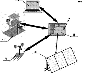 |
The overall system is presented in fig. 1. The complete strategy is composed by 5 sub-systems: 1) Electro-Mechanical Structure; 2) Control Unit; 3) Supervisory System; 4) Wind-meter; 5) Photovoltaic Park.
The degree day method is a simple approach which can be used to quickly calculate the heating or cooling energy consumption of a building and is recommended in the ASHRAE Standard Methods of Measuring, Expressing and Comparing Building Energy Performance to compare energy performance of buildings [8]. The HDD are calculated by multiplying the difference between the ambient air temperature and a certain base temperature by the time spent at this temperature. The heating degree days were calculated from the Sydney TMY2 weather data used for the simulations. This showed that Sydney had 760 HDD [K. d/a] per year assuming a base temperature of 18 °С. Hart and Dear [9] examined the mean daily temperature associated with the minimum heating and cooling energy consumption for Sydney and found that a degree-day base temperature of 18 °С is appropriate to use for the calculation of both heating and cooling degree-days. The number of heating degree days for Sydney as determined from the TMY2 weather data are shown in Table 2. Table 2. Monthly breakdown of heating degree days for Sydney
|
Month |
Jan |
Feb |
Mar |
Apr |
May |
Jun |
Jul |
Aug |
Sept |
Oct |
Nov |
Dec |
|
HDD [K. d/month] |
2 |
1 |
6 |
30 |
74 |
146 |
178 |
150 |
96 |
47 |
25 |
5 |
The following equation was used to calculate the monthly heat transmission energy requirement, Qreq = (UA)eff X HDD X 24 (1)
where Qreq is the simple transmission heat energy required and (UA)eJf is the U-value multiplied by the external area of the building. The following equation was used to calculate the monthly ventilation heat loss energy requirement,
Qvent = ACH X Vair X Cp air X HDD x 24 (2)
where Qvent is the heating demand energy loss due to ventilation and infiltration, ACH is the air change rate for the building, Vair is the air volume, and Cp air is the specific heat capacity for air.
Internal gains of 3W/m2 were assumed and the solar gains through the windows, the monthly utilisation factor and the resulting heating demand were calculated using the following equations,
where nutilisation is a simple approximation for the utilisation factor for the whole heating period, Qgains is the sum of the internal and solar gains, Qlosses is the sum of the heating transmission and ventilation losses and Qdemand is the heating requirement of the house.
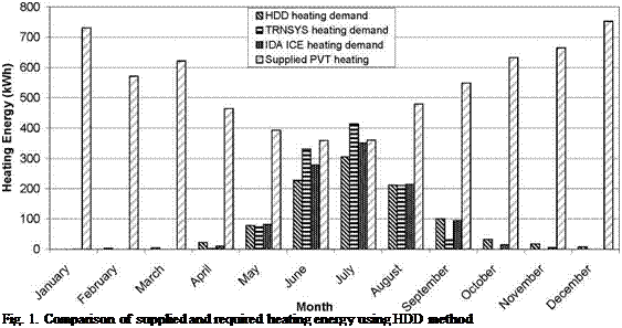 |
From the simulations conducted in TRNSYS and the PVT performance equations the PVT system was found to have a thermal efficiency of up to 27%, however the average efficiency of 22% was used to calculate the supplied PVT heating. The results of the simple HDD calculations are shown in Figure 1 below. This graph shows that heat removed from a 16m2 (1.6 kWp) PVT array will meet the HDD heating requirement of a well insulated Sydney house in winter but in the month of July the TRNSYS heating demand is greater than the heating supplied by the PVT system. The heating demand as calculated in the IDA ICE and TRNSYS simulations included in this graph show good agreement with the simple HDD calculations. More detailed analysis is required to determine the day to day heating effect of the PVT system.
Bernhard Wille-Haussmann*, Thomas Erge, Jochen Link, Christof Wittwer
Fraunhofer-Institut fur Solare Energiesysteme ISE, Heidenhofstrafle 2, 79110 Freiburg, Germany
Corresponding Author, bernhard. wille-haussmann@ise. fraunhofer. de
Abstract
To integrate high volumes of renewable and decentralised energy resources (RES & DER) into the electricity grids it will be necessary to manage generation and loads much more than today. Within this paper we discuss operation strategies for cogeneration plants, which can contribute to active grid management with high volumes of RES. Typically cogeneration plants (CHP) are thermally driven, which is enforced through guarantied fixed feed-in tariffs (e. g. the KWK-G feed in tariff in Germany). With the growing share of CHP up to 25% of electricity production in 2020 (18% EU [1]), the rules of control devices increase and the feed-in tariffs are expected to change to a flexible structure. To manage cogeneration in the distribution grid we investigated additive variable local tariff components for the electricity production. The influences of different CHP operation strategies to the power quality are evaluated in a load flow simulation of an exemplary low voltage grid. The results show that with the local tariff based operation a bigger part of the electric load profile is covered by local generation and also the variation of voltage in the grid decreases.
Keywords: cogeneration, optimised operation, load flow analysis
1. Introduction
Driven by the liberalisation of the electricity markets and the support for distributed, climate friendly generation technologies, the production system of electricity develops more and more from a centralised to a decentralised structure. Especially lower voltage levels are faced with supply by distributed and/or fluctuating power plants (RES), such as photovoltaic, wind and cogeneration. This leads to new operation requirements in the grid. Management strategies for those grids with a high penetration of DER must be developed [2]. To integrate a great amount of these technologies, the grids will not be allowed to stay passive. They must become active and communication between the different participants is necessary. Those “smart grids” should be designed and managed by model based methods.
Cogeneration plants produce heat and electricity simultaneously. Due to the fact, that electric and thermal demand profiles do not match, a thermally driven CHP can not supply electricity peak demands when needed. With thermal storage systems it is possible to decouple the electric and thermal delivery, which offers a higher degree of freedom for the operation management. In contrast to most renewable generators, whose production fluctuates with the availability of sun or wind, cogeneration plants can be used quite flexibly, as long as the thermal restrictions are respected. This fact offers the possibility to use them in the grid to stabilise the power quality, e. g. the voltage range. With a high
penetration of RES the number of factors to be considered by grid management increases enormously. To manage those complex grids new optimisation and model reduction techniques are necessary to get rid with the complexity. Within the project NetMod [3], which is supported by the German “Bundesministerium ftir Bildung und Forschung”, together with several partners Fraunhofer ISE develops methods for such a management.
 |
In this paper we discuss integration and management strategies for RES in a showcase of a low voltage grid. The structure of this grid is shown in Fig. 1. The grid consists of a long branch which feeds several houses in a rural area. Typically these structures are dimensioned weak, so that the high potential of renewable generation in this area is limited by the transport capacity of the local grid. For this showcase we assumed 4 houses with a nominal power of 10 kW each. At each house also one PV plant with a peak power of 25 kWp is installed. At the last house also a CHP plant with a nominal electric power of 25 kW (pel = 30 %, pth = 65 %) is installed, which supplies a local heat grid. To increase the degrees of freedom for each CHP a thermal storage with a capacity of 3000 l is installed.
In the following chapter we will discuss several possibilities to operate cogeneration plants. Based on this we introduce an optimisation algorithm for CHP operation, which is based on variable tariffs. For the showcase two price functions (global and local) are introduced. The operation of cogeneration only makes sense if the produced thermal energy can be used simultaneously or can be stored for a later use. There fore knowledge about the thermal load profile is necessary to generate optimal schedules. The prognosis of the thermal load will be subject of the following paragraph. Decentralised generation will influence the power quality in the grid. The following chapter evaluates the influence of different operation scenarios to the power quality by a load flow analysis and closes with suggestions for a grid optimised operation of decentralised power plants.
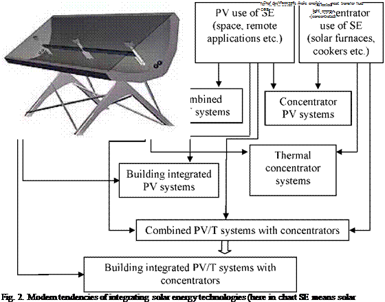
Silicon cells are the most expensive element used in photovoltaic systems. This reason and shortage of monocrystalline silicon lead us to developing concentrator approach.
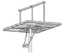
There are a number of companies already acclaims about producing concentrator PV/T systems. Among them are Swedish cleantech company Arontis AB (Solar8, Fig.3, left), Canadian company Menova Energy Inc. (Power Spar, Fig.3, right), Spain company TRIGEN Solar S. L (GSH-20X, Fig.4, left), UK company HelioDynamics (HD16c with possible applications, Fig.3, right) [4].
Concentrator PV/T system built in the framework of research VEI project consists of 2D rotational frame, concentrator made with flat mirror facets and PV/T receiver. The project is devoted to
 |
designing, building and testing of PV/T concentrator system based on solar cells with vertical p-n — junctions (Fig. 5).
Fig. 3 Solar8, left and Power Spar, right.
 |
 |
 |
|
Fig.4. GSH-20X, left and HD16c with possible applications, right.
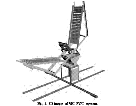 |
PV/T receiver includes row (array) of solar cells with vertical p-n-junctions in a case with quartz windows and special cooling liquid inside. PV/T receiver is designed for two side illumination because of ideal symmetrical design of solar cells with vertical p-n-junctions.
1.2. Solar cells with vertical p-n-junctions
Receiving element and solar cells for it are most important parts of concentrator PV/T systems.
The solar cells with vertical p-n-junctions are known as a good alternative of planar concentrator solar cells. They have a number of advantages: high temperature tolerance, low series resistance, bifacial sensitive accepting surfaces suitable for bifacial illumination, low equilibrium temperature,
quite simple technology of manufacturing etc. Low series resistance gives them to work under high concentration ration.
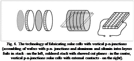
A method of manufacturing solar cells with vertical p-n-junctions using thermal compression bonding with silumin was developed in VEI and defended by Russian patents [5, 6]. The main goal of this technology is to provide a structure for a photovoltaic cell which gives as a result improved characteristics: improving quality of interconnecting soldering, eliminating of compensative influence of aluminum to n-layers, high temperature tolerance and mechanical firmness. The main stages of technology of producing solar cells with vertical p-n-junctions (without antireflection coating) are showed at Fig.6.
According to our approach, the silumin (alloy of Al and Si) layers prevent a penetration of compensative impurities (Al) into n — region. The produced solar cell structures give as a result the high quality mechanical and electrical contacts, high fill factor for I-V-characteristic (more than 0.8), and increased tolerance to high temperature under high intensity and higher tolerance to penetrating particle radiation (for space applications).
For optimization of technology processes the modern high resolution scanning microscopy methods of investigating vertical p-n-structures are used.
A model was constructed for computation of the maximum power point output of a photovoltaic system from radiation components on the horizontal plane, based on general transposition formulas for beam radiation, the Hay and Davies model for diffuse radiation and assumed seasonal variations in ground reflectance [12]. All radiation components are modified by an incidence angle modifier, expressed by [13], that depends on the effective angles of incidence. The conversion efficiency of the photovoltaic array, dependent on ambient temperature and standard NOCT measurements for solar cells, was modeled from [12]. Standard silicon solar cell parameters were
used and temperature and radiation data were generated for Stockholm with the climate database program Meteonorm 6.0. [14].
Luis Ricardo Bernardo*, Bengt Perers, Hakan Hakansson and Bjorn Karlsson
Energy and Building Design Division, Lund Technical University, Box118 SE-221 00 Lund, Sweden
* Corresponding Author, Ricardo. Bernardo@ebd. lth. se
Abstract
The purpose of this study was testing and performance simulation of an innovative tracking hybrid solar system being developed by the Swedish Company Arontis. The Solar8 collector produces both electrical and thermal energy in one system. Its performance was compared with conventional photovoltaic panels and solar thermal collectors working side-by-side which are already on the market. The solar8 sample tested in Lund is a prototype designed for small demonstration projects and further development is ongoing.
The evaluation shows that the thermal collector has an overall heat loss coefficient of 3.1 W/(m[5] [6].°C), an optical efficiency of 65% and an electrical efficiency at 25°C of 8% per active glazed area. If we account the total glazed area instead, the thermal collector has an overall heat loss coefficient of 2.5 W/(m2.°C), an optical efficiency of 52% and an electric efficiency at 25°C of 6%. The electric efficiency of the bare cells is 16%. Annual performance simulations were carried out for the Swedish (Stockholm), Portuguese (Lisbon) and Zambian (Lusaka) climate. From the simulations one can conclude that: Solar8 can be replaced by a traditional PV-thermal collector side-by-side system using less space and producing the same electric and thermal outputs; tracking around one axis placed in North-South direction is considerably better then tracking around an axis set on East-West direction; the global irradiation on a static surface is always higher when compared with the beam irradiation towards a tracking concentrating surface; the ratio between electric and thermal output decreases when Solar8 is moved to the equator.
Keywords: Solar8, Solar Hybrids, Photovoltaic Thermal Concentrators, PVT
 |
output is limited by the output coming from the poorest cell since all the cells are series connected. This is one of the challenges to overcome in this new technology. Local diodes installed in each cell can be able to bypass the current over the poorest cells and help reducing the problem with uneven radiation.
It is important to notice that the production of both heat and electricity is favoured by lowering the operating temperature. However a minimum water temperature is generally required by the given application involving higher working temperature on the cells. Due to lower insulation, the hybrid system thermal losses are higher when compared to a normal solar collector. Hence, it is expected that a flat plate hybrid system will deliver approximately 10% less electricity and 10% less heat compared to a thermal collector beside a PV module with the same cells amount [1]. It is also important to have in mind that when an electric load is connected to the PV cells, the thermal efficiency is further decreased since part of the radiation is converted into electricity. [7]
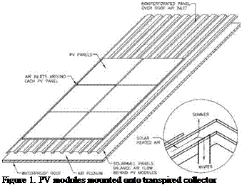
The testing at NSTF was done indoors with a solar simulator and included panels from three manufacturers, BP Solar, Evergreen Solar and UniSolar. These tests were conducted on the 10
 |
 |
square metre (108 ft2) test panel previously used for certification tests of the SolarWall solar air heating system.
Evergreen supplied six of their new 170 Watt panels. Two rows of three panels covered 90% of the 10 m2 test panel.
BP Solar supplied six of their 160 Watt panels which when placed onto the test panel covered approximately 76% of the test panel surface leaving 24% of the transpired panel exposed to the sun.
UniSolar supplied eight of their peel and stick 68 Watt modules which fit onto the test panel in a horizontal configuration and covered 90% of the test panel.
It was decided to perform two sets of tests at two flow rates for each panel, one set at NOCT conditions and the other at the solar thermal conditions. The air flow heat removal rates selected were 36 m3/h. m2 (2 cfm/ft2) and 108 m3/h. m2 (6 cfm/ft2) of gross collector surface which represent low and medium air flows typical for heating ventilation air.
The Evergreen panels and UniSolar panels have similar coverage area of 90% but are significantly different in shape. The Evergreen and BP panels are similar type and shape with the main difference being the coverage area, BP panels only cover 76% of the surface of the transpired panel compared with 90% for the Evergreen ones.
 |
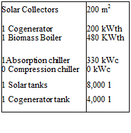
An excel sheet has been created including a methodology to size each machine, heat exchanger, tank and pump of the selected layout. The outputs of this procedure are used for first simulations to assess the performance of the overall system. Depending on the outcome of the simulations, the procedure is repeated and followed by further simulations with the aim to find out the optimal sizes.
First, the sizing procedure requires the selection of the DS, as this choice fixes the hot and cold streams temperatures to be provided by the facility. As already mentioned, radiant panels (40/30 °C) and fan coils (8/13 °C) have been respectively selected for heating and cooling. Secondly, the heat and cold power demand of a user building is needed. As previously said, the monitored heating and cooling power demand of EURAC has been given as input to the sizing procedure. Then, the following main steps are implemented:
• The summer heat demand is calculated on the basis of the cooling load rate that is wanted to be supplied by an absorption chiller and of a typical COP of such machine;
• On the basis of the duration curve (Fig. 3.), the co-generator size is selected in order to ensure 3000 running hours per year at least;
• The biomass boiler size is obtained by the maximum requested heat power minus the heating capacity of the cogenerator;
• The heat exchanger between the facility and the DS is sized depending on the needed heating and cooling power and the desired logarithmic temperature differences, thus the maximum flow rate in the overall facility is determined;
• The mass flows for all the machines are calculated on the basis of their capacities and the temperature gaps they have to provide.
For determining the values to be assigned to some variables, such as the collectors surface and the storage tanks capacity, no defined calculation procedure is applied as this selection can depend on practical aspects, e. g. the maximum building surface which is exposed to the sun for the collectors or the available volume space for the tanks.
 |
 |
The outcomes of the first application of the sizing procedure are used for the first simulations (Fig. 5.): they only represent a starting point for the optimization process, especially for the solar collectors surface, the storage tanks and the absorption chiller size.
Fig. 5. First selection of sizes and simulation of the heating flow demand and of the flows deriving from each
heat production system in a typical winter day.
The operational subset of the tracking system, named Electro-Mechanical System, is presented in figs 2 and 3.
This structure has two DOF, motorized by stepper motors with incorporated encoders, in order to track exactly the prescribed path.
The mechanical system was designed using standard industrial Aluminium profiles in order to obtain a simple and economic structure.
The mechanical structure is mainly composed by Bosch-Profiles and Aluminium plates.
The two motorized axis are composed by Step-motors assembled to Aluminium shafts.
Figure 2 illustrates the several main components of the mechatronic system:
Part n. 6 = Step-Motor to control axis 1;
Part n. 7 = Step-Motor to control axis 2;
Part n. 8 = Photovoltaic cell (150mmx150mm).
The PLC-tracker has the complete operational management of the tracking system. The main tasks performed by the system are:
— Control of the two step motors;
— Processing the data from both encoders;
— Processing the voltage signal coming from the PV-Cell;
— Processing the data from the external proximity sensors that informs the system about the hard-home position reference.
This PLC controls directly the tracking system and commands all other PV-Panels, from the solar Park, according to the developed algorithm. Figure 5 shows an example of a solar park with several PV-Panels.
 |
A model of the house was constructed in both TRNSYS and IDA ICE, allowing comparison of the heating demand simulated by each program. Figure 2 shows the 3D visualisation of the house created in IDA ICE.
The heating energy requirement of the house is determined by implementing a heater with unlimited heating capacity in each zone, setting the mean indoor temperature to 18°C and modelling the house separately from the PVT system. The simulation results for the heating energy delivered to the zones then provide values for the energy required by the zones to maintain an average temperature of 18°C. Heat gains of 3W/m2 due to lighting, equipment and occupancy were included in the modelling. An air change rate of 1 ACH was used for all simulations.
In order to determine the output energy from the PVT system that could be supplied to the house, the TRNSYS Type 567 PVT system was also simulated separately using TMY2 weather data for Sydney and the parameters detailed in Table 1.