Как выбрать гостиницу для кошек
14 декабря, 2021
An excel sheet has been created including a methodology to size each machine, heat exchanger, tank and pump of the selected layout. The outputs of this procedure are used for first simulations to assess the performance of the overall system. Depending on the outcome of the simulations, the procedure is repeated and followed by further simulations with the aim to find out the optimal sizes.
First, the sizing procedure requires the selection of the DS, as this choice fixes the hot and cold streams temperatures to be provided by the facility. As already mentioned, radiant panels (40/30 °C) and fan coils (8/13 °C) have been respectively selected for heating and cooling. Secondly, the heat and cold power demand of a user building is needed. As previously said, the monitored heating and cooling power demand of EURAC has been given as input to the sizing procedure. Then, the following main steps are implemented:
• The summer heat demand is calculated on the basis of the cooling load rate that is wanted to be supplied by an absorption chiller and of a typical COP of such machine;
• On the basis of the duration curve (Fig. 3.), the co-generator size is selected in order to ensure 3000 running hours per year at least;
• The biomass boiler size is obtained by the maximum requested heat power minus the heating capacity of the cogenerator;
• The heat exchanger between the facility and the DS is sized depending on the needed heating and cooling power and the desired logarithmic temperature differences, thus the maximum flow rate in the overall facility is determined;
• The mass flows for all the machines are calculated on the basis of their capacities and the temperature gaps they have to provide.
For determining the values to be assigned to some variables, such as the collectors surface and the storage tanks capacity, no defined calculation procedure is applied as this selection can depend on practical aspects, e. g. the maximum building surface which is exposed to the sun for the collectors or the available volume space for the tanks.
 |
 |
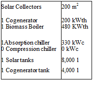
The outcomes of the first application of the sizing procedure are used for the first simulations (Fig. 5.): they only represent a starting point for the optimization process, especially for the solar collectors surface, the storage tanks and the absorption chiller size.
Fig. 5. First selection of sizes and simulation of the heating flow demand and of the flows deriving from each
heat production system in a typical winter day.