Как выбрать гостиницу для кошек
14 декабря, 2021
Сегодня каждый, кто собирается в отпуск и не знает, с кем оставить своего котика или кошку, может во[...]
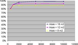
A parametric study has been carried out, in which the solar fraction of a thermochemical storage system for a low-energy house (6 GJ space heating) with a 40/25C low-temperature heating system and 9 GJ domestic hot water) was calculated as a function of collector area, collector type, charge and discharge temperatures, charge and discharge power, and reactor heat capacity and insulation (Zondag et al., 2008). Some typical results are displayed in Fig. 3 and Fig. 4. These calculations show an idealised case, in which good vacuum tubes were used, as well as a collector piping loop without heat loss, 100% efficient backup heaters and optimised TCM material (very fast reaction kinetics, ideal conductivity, small temperature hysteresis). All areas in the graphs refer to aperture.
SHAPE * MERGEFORMAT

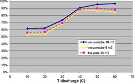
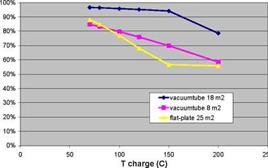
Fig. 3. Solar Fraction versus charge and discharge temperatures of TCM storage
|
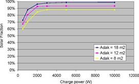
• The effect of the charging temperature of the TCM on the system performance depends strongly on the type of collectors used and the system dimensioning; generally, good vacuum tube collectors are preferred for TCM charging, since relatively high charging temperatures have to be reached. In addition, the simulations show that if the collector array is dimensioned large, an increase in the required TCM charge temperature only reduces the number of standstill hours, without much effect on the solar fraction. However, if the solar collector array is dimensioned small, an increase in required TCM charge temperature will imply that the storage is not filled anymore, thereby substantially reducing the solar fraction that can be obtained (see Fig. 3b).
In addition, the effect of the thermal capacity of the TCM reactor was investigated. It was found that the insulation of the TCM reactor was increasingly critical for reactors with a high thermal capacity, the worst case being that of a reactor integrated into an insufficiently insulated non- compartimented storage (as shown in Fig 1b).
For a wide range of Aquaculture facilities operational temperature must be 24°C during winter. This section shows the simulation for a Solar Pond with a 1000 m2 area and 2 m depth, considering that variables ambient temperature, energy extraction and solar radiation at surface are sinusoidal like in the work presented in [7].
In order to a better knowledge of the simulation we consider two years of Pond performance even operational DSP will be operated at an annual periodicity basis. Energy extraction will be the important criteria to achieve the temperature level of the SZ.
For an example application in the Portuguese west coast (Lat 38N) which leads to the ambient temperature presented in model we are going to consider three regimes of DSP energy extraction.
|
120 |
|
40 |
|
20 |
|
-Tsz |
|
Tamb |
|
-Qext I |
|
100 |
|
80 |
|
60 |
|
0 |
|
Fig. 2 — 1000m2 Solar Pond high level energy extraction. |
 |
Considering an high rate of energy extraction the temperature in the storage zone varies between 20° C and 65°C achieving not the desirable minimal winter temperature for the example application (Figure 2).
|
0 5 10 15 20 25 t [month] I Tsz Tamb Qextl |
|
120 100 80 60 40 20 0 |
|
CD O’ |
|
Fig. 3 — 1000m2 Solar Pond low level energy extraction |
 |
For the situation of virtually no energy extraction, the temperature raises more than 100°C, which leads to a quickly homogenization of the Pond (Figure 3).
This example is not adequate with the operation of a Solar Pond. If it is going to boil the zones became homogeneous and the Solar Pond destabilized. So neither these situations are in agreement with the expectations for an application.
|
Tsz |
|
10 15 t [month] Tamb Qextl |
|
20 |
|
25 |
|
x CD O’ |
|
0 |
|
5 |
 |
A third situation seems to be adequate to achieve Aquaculture thermal demand. Here the level of extracted energy is slowly less but the temperature in the storage zone is in a proper range, 25°C to 75°C (Figure 4).
Fig. 4 — 1000 m2 Solar Pond adjusted level energy extraction.
C. F. Tavares1*, J. M.P. Coelho2, D. Castro Alves2, M. Abreu2, A. M. Joyce1, E. C. Fernandes3
1 INETI, Dept. of Renewable Energies, Campus do Lumiar do INETI, 1649-038 Lisbon, Portugal
2 INETI, Dept. of Optics and Laser, Campus do Lumiar do INETI, 1649-038 Lisbon, Portugal
3 IST, Dept. of Mechanical Engineering, Av. Rovisco Pais, 1049-001 Lisbon, Portugal
* Corresponding Author, :elia. tavares@.ineti. pt
The gradient zone of salt gradient solar pond is a double diffusive system where instabilities can appear leading to the reduction of the performance of the pond. To better understand double diffusive instabilities a double diffusive layer was studied in laboratory. An initial stable salt stratified layer was heated from bellow to a prescribed temperature and the evolution of the system was analysed. Shadowgraph and Particle Image Velocimetry (PIV) techniques were used to identify and to study the evolution of convective and diffusive zones, to obtain instantaneous whole field velocities measurement and to analyse the effect of convection on the behaviour of the neighbouring densities interfaces. The evolution of the temperature and salinity profiles was also recorded along time to analyse the stability criteria that lead to the transition of diffusive regime to convective regime. Experimental buoyancy ratios show good agreement with Veronis’ stability criteria. For high imposed temperature and a comparative weak density gradient, vigorous convective layers separated by thin interfaces produce great instabilities and a rapid destruction of the diffusive zones. On the other hand, when the linear solute gradient is strong the system develops quasi-stationary states where the interfaces remain stable for a significant period of time.
Keywords: solar pond, double-diffusive convection, flow visualization, stability
A salt gradient solar pond is an artificial device used to collect and store solar thermal energy. A non-convective zone in the middle of the solar pond allows a significant rise of temperature in the lower zone where the solar thermal energy is stored. This is an attractive and low cost solution to capture and store solar thermal energy, in a seasonal way, due to easy construction with few resources needed. The surface area of a solar pond can vary between few square meters to thousands of square meters. Nowadays, solar ponds with a surface area of few square meters and few centimetres of depth are being developed for different thermal application like, for instance, desalination [1].
The main key to the working of a solar pond is the non-convective zone, also named gradient zone. The gradient zone works like an optical thermal insulator reducing the loss of heat collected in the lower zone of the pond (the storage zone), since the water has low thermal conductivity and is opaque to infra-red radiation.
The non-convective zone is characterized by the presence of two gradients, the salinity and the temperature gradients, both having an opposite effect to the stability of the non-convective layer. The salinity gradient increases the density with depth, promoting the stability of the layer, while the temperature gradient has an adverse effect that counteracts the density gradient. The different
molecular diffusivities of heat and mass and the opposing effects on the vertical density distribution of the temperature and salinity gradients can lead to local destabilization that could cause local convective motions, even with a statically stable density gradient. This kind of instabilities is named double-diffusive convection. The appearance of these convective zones weakens the insulator feature of the solar pond and reduces pond’s efficiency. To predict and prevent the onset of convective motion in the gradient zone it is important to understand double diffusive process and the condition for the change of diffusive regime to convective regime.
It should be remarked that double (or multiple) diffusive convection phenomenon takes place in other engineering systems and processes like crystal growth, liquefied natural gas storage tanks and nuclear engineering, in different domains, like oceanography, astrophysics and geology and in several practical applications like pollution and thermal environment control of buildings [2].
One of the topics of double diffusive systems is the study of the behaviour of the double diffusive layer under stability criteria, i. e., the physical conditions, regarding temperature and salinity profiles, from which instabilities can appear leading to oscillatory movements that could produce convective regimes. Veronis [3] defined that stability depends essentially on the following dimensional numbers: the thermal and salinity Rayleigh numbers, Ra and Rs, respectively, the Prandtl number, Pr, and the Schmidt number, Sc. The ratio between the Pr and Sc, t, is for NaCl aqueous solution equal to approximately 10-2, (t = Pr/Sc => t = KS/KT) showing that the thermal diffusivity (KT) of this salt is one hundred greater than the molecular diffusivity (KS). The relation between Rs and Ra is named density stability ratio, or buoyancy ratio, Rp, and is defined as:
|
(1) |
![]() Rs 0AS
Rs 0AS
— ^ RP =——
Ra p aAT
where AS and AT are the salinity and temperature differences between the top and the bottom of the gradient zone, and a and p are the coefficient of thermal and saline expansion coefficient. The theoretical analysis of Veronis of the behaviour of double diffusive layers under stability criteria gave the following marginal states equations: for the onset of instabilities Ra=0.809Rs (i. e., Rp= 1.236), and for the onset of steady convective motion: Ra=43.16Rs (i. e., Rp= 0.023). More recent studies [4], which consider variation of flow properties and the effect of solar radiation absorption, led to the definition of some different stability conditions, more restrictive when non-constant diffusivities of molecular heat and salt and solar radiation absorption is considered simultaneously in the theoretical analysis.
Experimental studies of double diffusive layers were usually performed by heating from bellow an initial stable salt gradient which has a similar effect to solar radiation absorption in salt stratified layer. When a stable salt gradient layer is heated from below, a series of convective layers separated by thin density interfaces could be formed. Turner [5] was the first to perform, in laboratory, quantitative studies of this phenomenon, concentrating on the dynamics of the first mixed layer which appears near the heating surface, and the formation of the second layer above it. Huppert and Linden [6] extended this formulation to predict the evolution of the following layers. The density interfaces that separate convective layers from gradient zones, this last with more or less thickness, are subject not only to double diffusive instabilities but also to other types of instabilities, namely the effect of the adjacent convective motions. The rates of salt transported diffusively from the density interface and convectively into the mixed regions determine the evolution of the thickness and stability of these interfaces [7], and consequently the growth rate of convective zones.
The present work consists on the laboratory study of double diffusive systems. A salt stratified layer with an initial linear concentration gradient was heated from bellow at a prescribed temperature. With the present work the flow visualization technique Particle Image Velocimetry (PIV) [8] was implemented to obtain the velocity fields and the patterns of convective zones and Shadowgraph technique was used to identify the position of the interfaces. We present results of the evolution of a double diffusive layer, namely, the evolution of the salinity and temperature vertical profiles, and we compare these profiles with Veronis’s stabilities criterions. The effects of convective zones on the behaviour of densities interfaces are also analysed.
High purity grade alkali nitrates and alkali metal nitrites from Merck or Fluka were used (Table 3, right column). The mixtures were pre-melted in air atmosphere (typically at 400°C) and subsequently ground. The mixtures were kept dry in order to exclude effects from moisture.
For a preliminary examination of the salt systems, phase diagrams with the solidus and liquidus line were obtained by a melting point apparatus (Stanford Research Systems, OptiMelt MPA100). The system performance was verified and optimized by the measurement of the well known system KNO3-NaNO3. The impact of the heating rate was also examined and a rate of 1 K/min was selected. For each examined salt system several mixtures with different compositions were prepared and subsequently measured.
For some salt systems, more precise latent heat and melting temperature measurements were made with a heat flux type DSC (Netzsch DSC404) in argon flow (100 ml/min) with a heating rate of 10 K/min. As a crucible open platinum/rhodium pans with a lid were used. The first heating cycle was excluded from the analysis in order to exclude effects such as moisture.
|
600 500 (D 400 ro 300 E <D H 200 |
|
100 h———— ,——— ,————— ,—— ,————— ,———- ,—— ,——— ,————— ,———- , 0 10 20 30 40 50 60 70 80 90 100 |
|
— Liquidus (reproduced from Protsenko) Liquidus 150-170°C by DSC (DLR) — Liquidus by Melting point apparatus (DLR) Solidus by Melting point apparatus (DLR) |
|
Ba(NO3)2 [wt%] |
|
0 10 20 30 40 50 60 70 80 90 100 NaNO2 [wt%] |
 |
![Подпись: 0 10 20 30 40 50 60 70 80 90 100 NaNO2 [wt%]](/img/1128/image338.gif) |
Protsenko et al. reported a phase diagram of the Ba(NO3)2-KNO2 system [43]. The phase diagram by Protsenko and values obtained in this work are shown in Fig. 3 (left). The system has an eutectic point at about 50wt% Ba(NO3)2 and a promising melting temperature of around 170°C. DSC-Measurements of this eutectic composition gave a melting enthalpy of about 60 J/g. Besides this relatively low melting enthalpy, other disadvantages include the handling and the availability of KNO2, as well as the steep gradient in the liquidus line on the left and right hand side of the eutectic composition. For long-term and large scale use of the eutectic composition, it may be difficult to avoid the two phase area of the system due to the characteristic of the liquidus line.
Fig. 3. Phase diagram of Ba(NO3)2-KNO2 (left) and Ba(NO3)2-NaNO2 (right)
Literature data about the Ba(NO3)2-NaNO2 could not be identified. Fig. 3 (right) shows the phase diagram obtained by the melting point apparatus. The eutectic composition is around 60wt% NaNO2 with a minimum melting temperature of around 205°C. This melting temperature could be confirmed by DSC measurements with several melting cycles.
No phase diagram of the NaNO2-Sr(NO3)2 could be identified. The minimum melting temperature by DSC and melting point apparatus was between 190 and 195°C. The eutectic composition is estimated to be near 60wt% NaNO2 with a melting enthalpy of around 120 J/g.
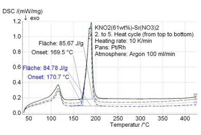
For the system KNO2-Sr(NO3)2, also no literature data could be identified. The minimum melting temperature by DSC and melting point apparatus was in the range 170 to 175°C with a eutectic composition near 60wt% KNO2. The liquidus line was less steep near the minimum melting temperature compared to the Ba(NO3)2-KNO2 system. DSC-measurements of the 61wt%Sr(NO3)2- KNO2 resulted in an melting enthalpy of about 85 J/g (Fig. 4).
|
Fig. 4. DSC-Measurement of four melting cycles of KNO2(61wt%)-Sr(NO3)2. |
1.1. Results of the laboratory measurements [2]
All storage solutions dealt with in Subtask C were only laboratory prototypes. Measured results and projected heat storage densities for units of 70 and 1000 kWh storage for single family houses are reported. The prototypes use either paraffins or sodium acetate trihydrate, but all of them had a phase change at about 58°C in order to provide space heating and domestic hot water. The system from HEIG-VD additionally uses a PCM with phase change at 27°C in the preheating zone of the buffer store.
The prototypes are intended for different applications. While the stores from HEIG-VD, Switzerland and University of Lleida, Spain are short term heat storages for solar combisystems, the store from the Technical University of Denmark is used as seasonal storage by making use of the subcooling effect in hydrated salts. The work of Graz University of Technology is dealing with very short term storage for boilers, to reduce start-stop cycles and emissions. For small short term storages one decisive factor is to deliver enough thermal power for the domestic hot water demand (26 kW e. g. for filling a bath tub of a single family residential building). This means high specific power and therefore either high thermal conductivity of the solid PCM and/or small distances for the heat transfer from PCM to the heat carrier. For larger stores this problem is far smaller due to the lower necessary specific power. The projects were financed partly from national and partly from European Union projects.
The storage density compared to water is strongly dependent on the temperature lift in the storage tank. For small temperature differences (50 — 70 °C) and a bulk PCM tank with immersed heat exchanger (like the store used at the Graz University of Technology), the store can be theoretically sized about 1/3 of the volume compared to water, if sodium acetate trihydrate is used as PCM.
With this layout additionally about 20 kW thermal power can be delivered for the DHW production with less than 8 K heat loss. For the same PCM-material but macro-encapsulated and for a temperature lift from 25 to 85°C or 20 to 70°C in solar combisystems the store has the same size as a water store. For such cases there is even theoretically little benefit from PCM with respect to the store size.
In terms of material cost, all materials are expensive compared to water, ranging from pure sodium acetate with about 1 €/kg, paraffin with about 2 €/kg (including nucleation enhancer) to sodium acetate trihydrate with graphite and nucleation enhancers with about 3 — 4 €/kg. The cost for the whole storage system has not been estimated here.
The task will be organised around the following main activities:
• material engineering: analysis and engineering of advanced materials, synthesis of new materials and composites, and materials characterisation and testing;
• numerical modelling: numerical modelling of materials, including molecular interactions, mass and heat transport phenomena, and bulk behaviour;
• components and systems: development, numerical modelling, and testing of (prototypes of) thermal storage components and systems that use the materials developed in the other activities.
The main challenge for this task is to bring together material experts and application experts (particularly solar applications, given the primary scope of the task). The active participation of both groups of experts is essential for this task. However, these groups are traditionally organised in different Implementing Agreements. ECES, Energy Conservation through Energy Storage, has a strong tradition in material research, while SHC, Solar Heating and Cooling, has a strong tradition in solar applications.
Because of the particular nature of this task, a collaboration between these two Implementing Agreements is essential. Hence, this task will take the form of a Joint Task between these Implementing Agreements.
On October 5, 2007, a first expert meeting was held in Zurich, Switzerland, followed by a Task Defintion Workshop in Petten, The Netherlands, on April 10-11, 2008. Both meetings were very well attended, not only by researchers, but also by representatives of European industries, both large and small. Based on these meetings, the outline of the new task’s objective, scope, and main activities were defined. In a subsequent expert meeting in Bad Tolz, Germany, on June 4-6, 2008, the topics of the task were discussed in more detail.
One of the conclusions of these meetings wass that the main value in this task is to actively combine the knowledge of experts from materials science as well as from solar/renewable heating and energy conservation. Hence, a strong co-operation with other IEA Implementing Agreements is essential to the success of the task, as already mentioned above. Another noteworthy conclusion of the meeting was the strong interest of industry in this task: the industry representatives at the meeting all agreed on the importance of the development of new storage materials.
In their respective ExCo meetings in May and June 2008, the new task was officially approved by both the SHC and ECES Executive Committees. The task will be designated as Task 42 in SHC, and as Annex 24 in ECES. Both ExCos were very positive on the scope and topic of this task. Wim van Helden of ECN, the Netherlands, and Andreas Hauer of ZAE Bayern, Germany, were appointed as Operating Agents.
The official starting date for this four-year task is January 1, 2009. Although four years is relatively long compared to other tasks in either SHC or ECES, this is warranted by the fundamental nature of the work in this task. Because the work on advanced storage materials is still in a very fundamental stage, the trajectory towards applications is still relatively long. It takes several years to identify, characterise and optimise the right materials or composites, and again to develop the reactors, proof-of-principles, and prototypes of the advanced storages made of these materials.
Experts from industries and research organisations worldwide, that are active in this field, are cordially invited to join this new task. If you are interested, please contact the authors of this paper or your national ECES or SHC ExCo member.
More information on this task can be found on the temporary task website at www. ecn. nl/ieamaterials.
In the period 1996-2007 solar district heating plants were established at 6 places in Denmark. All projects were supported by the Danish Energy Agency and/or by The European Union and all plants consisted of ground mounted flat plate collectors of 12,5 — 14 m2 and has pumps with variable flow making it possible to decide a fixed production temperature from the solar collectors.
In the period the production price/MWh heat has been remarkable reduced for the same or higher solar fraction.
|
Plant |
Collector areal |
Established |
Production MWh/year |
Price Mio. € |
Solar fraction % |
Prod. price €/MWh Annuity 0,1 |
Prod. price €/MWh 2006 level |
|
Marstal |
8038 m2 |
1996 |
3472 |
2,23 |
13 |
64 |
87 |
|
^roskobing |
4890 m2 |
1998-2000 |
2103 |
1,24 |
16 |
59 |
83 |
|
Nordby |
2500 m2 |
2002 |
1100 |
0,63 |
25 |
57 |
63 |
|
Ulsted |
5000 m2 |
2006 |
2400 |
1,28 |
21 |
53 |
53 |
|
Bradstrup |
8000 m2 |
2007 |
3729 (calculated) |
1,68 |
9 |
45 |
44 |
|
Table 1. Price development 1996-2007 (examples calculated without investment support) |
Marstal combines solar with waste oil. ^roskobing combines solar with straw, Nordby combines solar with wood chips, Ulsted combines solar with wood pellets and Bradstrup combines solar with natural gas utilised in a combined heat and power (CHP) plant.
|
Fig 1. Brsdstrup implemented 2007 |
 |
The latest development in natural gas price has now resulted in implementation of one more solar district heating plant combined with natural gas fuelled CHP in 2008 and two plants are ordered for 2009 and more plants are expected to follow. These plants are implemented without economical support.
J. Cadafalch
Universitat Politecnica de Catalunya (UPC), Departament de Maquines i Motors Termics (MMT), Escola
Tecnica Superior d’Enginyeria Industrial i Aeronautica de Terrassa (ETSEIAT),
c/ Colom 11, 08222, Terrassa, Spain, e-mail: jcadafalch@mmt. upc. edu
Abstract
This work presents publishable information of the European-Craft project “OPICS — Optimised Integrated Collector Storage: Low-Cost Solar Thermal Systems for Houses and Offices” that finished on 2005. The project was funded in part by the European Commission and involved the companies DISOL and FOELCA from Spain, CIVILMAC from Portugal, SUNSTRIP from Sweden and UPC University. More than 7000 different configurations of integrated collector storage systems (ICSs) were simulated investigating different parameters such as the absorbing surface, single glazing, transparently insulated covers or water and phase change material store. Pre-industrial OPICS prototypes were constructed and tested following ISO procedures to assess the credibility of the results. Researched carried out proved that improved efficiencies can be achieved in the OPICS prototypes with respect to standard ICSs, and that they can be used in applications where standard ICSs are not able to give a reasonable performance such as space heating in moderate climates.
Keywords: DWH, ICS, TIM, PCM
The integrated collector storage (ICS) is a solar thermal system in which the functions of collection and storage of solar energy are performed within the same device. The integration of collector and storage elements leads to compact equipment simplifying the connection pipes and avoiding the use of intermediate elements such as pumps. Therefore, ICS is one of the simplest and cheapest solar thermal systems. In fact, the first thermal solar systems constructed were ICSs and during all the XXth century this kind of systems were installed all over the world.
As in the ICS the thermal storage is directly exposed to the ambient, the system heat losses are high. This problem, together with other problems always inherent in solar thermal systems as freezing of the thermal fluid or overheating, have limited up to now the applicability of the ICS to domestic hot water applications of familiar houses in warm climates.
Technologies as transparent insulation materials (TIM) and phase change materials (PCM) make it possible to improve the performance of the ICS maintaining low costs. Transparent insulation materials allow reducing the thermal loss through the cover while preserving good optical performance, and phase change materials can increase the energy storage in the collector avoiding overheating and freezing problems.
The design, study and optimisation of ICSs is much more difficult than the study of other solar thermal components, because many different complex and coupled physical phenomena are involved in only just one device: radiation heat transfer with spectral and angular dependence, heat conduction in the solid parts, heat convection in the thermal fluid in the storage tank and in the air
cavities, heat storage, etc… This difficulty is even increased when new technologies such as TIM or PCM are used.
One the other hand, one of the major drawbacks to be solved in solar thermal is the integration of the equipment in buildings. Most solar thermal systems and elements do not take into account the shape and the design of the buildings in which they will be installed, and generally the occupied space is not optimised and the visual impact is very criticised specially from architectonical points of view.
An European-Craft project called “OPICS-Optimised Integrated Collector Storage: Low-Cost Solar Thermal Systems for Houses and Offices” was carried out from 2002 to 2005. The project was funded in part by the European Commission and involved 4 European Companies (DISOL and FOELCA from Spain, CIVILMAC from Portugal and SUNTRIP from Swdend) and the UPC University, see [1].
The goal of the project OPICS was to develop Integrated Collector Storages with the following features:
• Use of Transparent Insulation Materials (TIM) and Phase Change Materials (PCM).
• Improvement of the efficiency with respect to available ICSs.
• Modular design to facilitate integration and to reduce installation costs.
Major developments of the project are two pre-industrial prototypes called OPICS1 and OPICS2. They both use a TIM-cover and have a modular rectangular shape that facilitates their integration in buildings. Main difference is the store. In the OPICS1, energy is stored in a 75 l rectangular water tank with internal mechanical elements to prevent deformation with pressure. On the other hand, in OPICS2 energy is stored in a rectangular PCM store with an internal compact heat exchanger that permits to remove the accumulated energy. The prototypes were designed using virtual prototyping tools [2,3] and were measured following standard procedures [4,5].
This work gives an overlook of the OPICS projected including the strategy, methodology, a description of the major developments and an assessment of the results achieved.
Stephanie HONGOIS1,2, Philippe STEVENS*3, Anne-Sophie COINCE1, Frederic KUZNIK2,
* author for correspondence
Email : philippe. stevens@edf. fr
1 EDF R&D, Department ENERBAT, Avenue des Renardieres, 77818 Moret sur Loing Cedex, FRANCE
2 CETHIL, Thermal Sciences Center of Lyon, UMR 5008, CNRS, INSA-Lyon, Universite Lyon 1, Bat. Sadi Carnot, 20 rue de la Physique, 69100 Villeurbanne, France
3 EDF R&D, Department LME
A seasonal chemical heat store, based on the hydration/dehydration cycle of a magnesium sulphate composite material, has been developed. During the summer, the material stores heat by an endothermic dehydration reaction and heat used for space heating is released in winter by rehydrating the material. The first elements for the sizing of the heat storage material tank have been calculated by modelling a conventional solar combisystem. For a low energy house of 191 m2 located in Paris, with a heat demand of 37.2 kWh. m-2 for space heating (53.0 kWh. m-2 including domestic hot water), the volume of magnesium sulphate required to reach a solar fraction ranging from 50 to 57 % varies from 0.2 to 0.9 m3. For the same house located in Marseille, with a space heating demand of 15.4 kWh. m-2 (31.1 kWh. m-2 including domestic hot water), a 100% solar fraction is achievable with a volume of 0.7 m3 of magnesium sulphate.
The hydration-dehydration reaction occurs at a gas-solid interface. In order to optimise the rate of reaction and the thermal power released or absorbed, the active material needs to be dispersed, which increases the volume of storage to an estimated 2 m3 to reach 50 % of the theoretical energy density of the dense salt. Composite materials made of magnesium sulphate are being developed at EDF R&D with the aim of reaching an energy density of 150-400 kWh. m-3 at a storage temperature compatible with solar thermal panels. The hydration of MgSO4/zeolite composites in an open system leads to higher temperature lifts and usable heat than MgSO4/silica gel composites.
Keywords: thermal energy storage, thermochemical storage, magnesium sulphate.
Most of the final energy consumed in France is used in the form of heat (85 Mtoe over a total of 161 Mtoe in 2004). Heat is also the largest part of the final energy used in buildings (around 46% of the total energy) and is responsible for 25% of the greenhouse gas emissions. It has therefore a considerable potential for energy savings and is a key element in the reduction by a factor of four of the GHG emissions by 2050 in Europe [1]. Coupled with actions to reduce existing dwellings heat demand through thermal insulation and better energy management, the use of high efficiency systems and renewable energy sources is necessary to fulfil this goal.
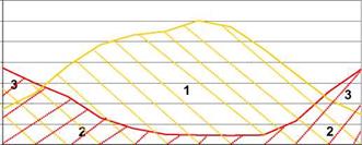
The available solar energy is huge, but the main difficulties lie in the diurnal and seasonal variations of the resource. Solar heat is available in excess in summer months, whereas a deficit occurs during the winter months (Fig. 1).
kWh / month
|
1 : Wasted energy 2 : Heat demand covered by solar energy 3 : Heat demand covered by auxiliary heating |

 3500
3500
_ 3000 .c
I 2500 E
^ 2000 £
1500
>
S 1000 c Ш
500
0
— Total heat demand of the building — Solar irradiation
Fig. 1. Monthly plot of total thermal energy demand vs. solar radiation on the collectors — House located in Paris
To overcome seasonal variations, a long-term storage should be designed. Thermal energy can be stored using one of three principles :
• sensible heat storage, based on a change in temperature of a material such as water, with a thermal energy density of around 70 kWh. m-3
• latent heat storage, based on the energy required or released during a phase change of a solid or liquid, with thermal energy densities between 40-100 kWh. m-3
• thermochemical heat storage, based on a sorption or a chemical reaction, with thermal energy densities between 150-1500 kWh. m-3.
The storage of heat using a chemical reaction is the most suited to seasonal heat storage because of the lack of thermal losses. Moreover, its volumetric energy density can be much greater than other forms of storage. During the summer, the material stores heat by an endothermic dehydration reaction whereas heat is released by rehydration in winter and used for space heating. Composite materials are being developed at EDF R&D with the aim of achieving usable energy densities between 150-400 kWh. m-3 at a storage (dehydration) temperature compatible with solar thermal panels.
Sizmann shows that the storage capacity is limited by it ability to take up entropy at a given temperature change [1]. This is also valid, if, in addition to the storage of sensible heat, the latent heat of a phase change can be utilized. The storage capacity can be increased significantly by the additional entropy change of the phase change [1].
In order to avoid the limitation by the achievable entropy uptake for “direct” TES systems (like sensible and latent), the entropy coupled to the heat supplied to the storage has to be separated. Such an “indirect” TES system is only storing work. It is now able to do this without any thermodynamic limitations.
However indirect TES are for discharging not independent as direct TES, where energy and entropy are available at the right relation. At discharging heat from the ambience has to be available to provide entropy for the heat release of the storage. This necessary connection to the ambience can be seen in figure 4 and 5. Advantages of such systems compared to direct TES are a higher flexibility concerning charging and discharging temperature and a higher storage capacity.