Как выбрать гостиницу для кошек
14 декабря, 2021
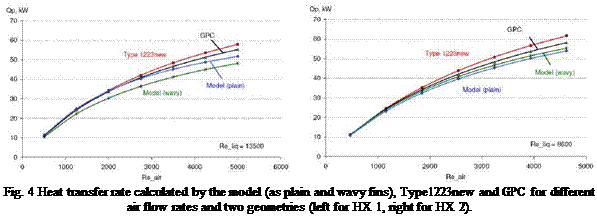
The model performance with 2 different airside correlations (Wang et al. [12] for wavy fins and Wang et al. [10] for plain fins) was compared with Type1223new and the producer design software Guntner Product Calculator (GPC) of the company Guntner GmbH. Two staggered tube lay outs available in GPC (HX 1 and HX 2, heat exchanger length of 1.25 m and height 1 m, 10 passes) with wavy fins (corrugation angle = 15°) were considered. For both geometries the heat transfer rate, calculated by the model with the correlation for wavy fins, is about 10% for HX 1 and less than 5% for HX 2 lower than that of the GPC, (Fig. 4). It has to be noted, that transverse tube pitch Pt in HX 1 is out of the validity range of the correlation for wavy fins, extrapolation of the correlation is in general not recommended. The heat transfer rate, calculated by the model for plain fins, is lower than the GPC heat transfer rate too (Fig. 4), which is plausible. However, HX 1 is also out of the validity range of the plain fin correlation, the deviation of this correlation to the GPC for HX 1 is even smaller than that of the wavy fin correlation, probably because of the less complex structure. Unlike these correlations, Type1223new with the Elmahdy and Biggs [5] correlation for plain fins gives higher heat transfer rate values than the GPC. It is, however, unfeasible that plain fins have higher heat transfer coefficient than wavy fins (compare with [20]).
 |
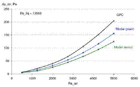
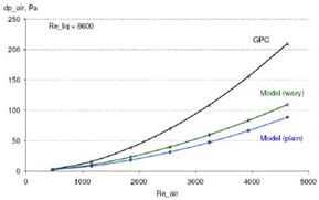
The airside pressure drop, determined with the correlations for plain and wavy fins, is significantly lower than that, calculated by the GPC, Fig. 5. Whereas liquid-side pressure drop calculation slightly overestimate the pressure drop calculated by the GPC and is in agreement with the GPC when calculated as smooth tubes.
 |
 |
Fig. 5 Airside pressure drop calculated by the model (as plain and wavy fins) and GPC for different air flow
rates and two geometries (left for HX 1, right for HX 2).
A model for fin-and-tube heat exchangers, which is based on empirical heat transfer and flow friction correlations, is presented here. The selected correlations are developed with larger data base and have complete description of the reduction method than the one used in Type1223new. In general one needs to be careful with empirical correlations, especially with complex ones, and one needs to prove simulation results. It is not recommended to extrapolate the correlations for configuration outside of the validity range. If configuration outside of the validity shall be simulated (e. g. for optimization of heat exchanger configuration) it appears to be sensible to use less complex correlations, e. g. Wang et al. [10] instead of Wang et al. [12].
The authors would like to express their gratitude to the Volkswagen Foundation, Germany for the financial support.
|
Nomenclature
|
[1] E. Frank, K. Vajen, A. Obozov, V. Borodin (2006): Preheating for a District Heating Net with a Multicomponent Solar Thermal System, Proc. EuroSun 2006, Glasgow
[2] Guntner GmbH (2007), personal communications.
[3] Brandemuehl, M. J., HVAC 2 Toolkit: A Toolkit for Secondary HVAC System Energy Calculations, ASHRAE 629-RP, Joint Center for Energy Management, University of Colorado, 1993
[4] Chillar, R. J, Liesen, R. J., Improvement of the ASHRAE secondary HVAC toolkit simple cooling coil model for simulation, Proceedings of the 1st SimBuild Conference, International Building Performance Simulation Association, 2004
[5] Elmahdy, A. H and Biggs, R. C., Finned tube heat exchanger: correlation of dry surface heat transfer, ASHRAE Transactions Vol. 85, Part 2, 1979
[6] Haaf, S., Warmeubergang in Luftkuhlern, pp. 435-491, in Plank, R., Handbuch der Kaltetechnik,
Springer Verlag, Berlin, 1988
[7] Wang, C. C., Chang, C. T. (1998), Heat and Mass Transfer for Plate Fin-and-Tube Heat Exchangers, with and without Hydrophilic Coating, Int. J. of Heat and Mass Transfer 41, 3109-3120
[8] Wang, C. C., Hsich, Y. C., Chang, C. T and Lin, Y. T. (1997), Performance of Finned Tube Heat Exchangers under Dehumidifying Conditions, J. Heat Transfer 119, 109-117
[9] Wang, C. C., Chi, K.-Y. (2000), Heat transfer and friction characteristics of plain fin-and-tube heat exchangers, Part I: new experimantal data, Int. J. of Heat and Mass Transfer 43 (2000), 2681-2691
[10] Wang, C. C., Chi, K.-Y., Chang, C.-J. (2000), Heat transfer and friction characteristics of plain fin-and — tube heat exchangers, Part II: Correlations, Int. J. of Heat and Mass Transfer 43 (2000), 2693-2700
[11] Wang, C. C., Lin, Y.-T., Lee, C. J. (2000), An airside correlation for plain fin-and-tube heat exchangers in wet conditions, Int. J. of Heat and Mass Transfer 43 (2000), 1869-1872
[12] Wang, C. C., Hwang, Y.-M., Lin, Y.-T. (2002), Empirical correlations for heat transfer and flow friction characteristics of herringbone wavy fin-and-tube heat exchangers, Int. J. of Refrigeration 25, 673-680
[13] Pirompugd, W., Wongwises, S., Wang, C. C. (2006), Simultaneous heat and mass transfer characteristics for wavy fin-and-tube heat exchangers under dehumidifying conditions, Int. J. of Heat and Mass Transfer 49, 132-143
[14] Jacobi, A. M., Park, Y., Tafti, D., Zhang, X. (2001), As assessment of the state of the art and potential design improvements for flat-tube heat exchangers in air conditioning and refrigeration applications — Phase I, Final Report. ARTI 21-CR Program Contract No. 605-20020
[15] Schmidt, Th. E. (1949), Heat transfer calculations for extended surfaces, Refrigerating Engineering, April 1949, 351-357
[16] Perrotin, T. and Clodic, D. (2003), Fin efficiency calculation in enhanced fin-and-tube heat exchangers in dry conditions, Proc. Int. Congress of Refrigeration 2003, Washington, D. C.
[17] Engineering Science Data Unit 86018 with Amendment A, ESDU International plc, London, 1991, pp. 92-107
[18] Shah, R. K. and Seculic’, D. P. (2003), Fundamentals of heat exchanger design, John Wiley & Sons Inc.
[19] Wagner, W. (2001), Stromung und Druckverlust, 5. Auflage, Vogel Buchverlag
[20] Gomini, G, Nonino, C. and Savino, S. (2003), Effect of space ratio and corrugation angle on convection enhancement in wavy channels, Int. J. of Num. Methods for Heat&Fluid Flow Vol. 13, No. 4, 500-519