Как выбрать гостиницу для кошек
14 декабря, 2021
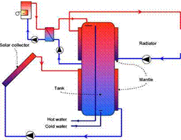
Schematic sketches of the investigated solar combisystems are shown in Fig. 1. In the solar combisystem based on a bikini tank, solar heat is transferred from the solar collector fluid to the domestic water by means of the mantle around the lower part of a hot water tank. Heat is transferred from the domestic water to the water in the space heating system by means of a mantle around the upper part of the hot water tank. The domestic hot water is directly tapped from the tank.
 |
 |
|
 |
||
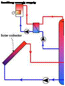
In tank-in-tank solar combisystem, a domestic hot water tank is integrated in the space heating heat store. Solar heat is transferred by the internal heat exchanger spiral placed at the lower part of the tank. The space heating system is connected directly to the tank. Domestic hot water tank is tapped from the domestic hot water tank in the store.
 b) Tank-in-tank solar combisystem
Fig. 1. Schematic sketches of the investigated solar combisystems
The thermal performance of the solar combisystems is calculated with the simulation program TRNSYS 16 [5]. The solar collector areas used are 3-8 m2. The collector tilt is 45° facing south. The
mass flow rate in the solar collector loop is 0.15 kg/min. m2 for the bikini solar combisystem and 1.2 kg/min. m2 collector for tank-in-tank solar combisystems corresponding to low flow and high flow systems. A differential thermostat control with one sensor in the outlet of the solar collector and one sensor in the lower part of the lower mantle for the bikini solar combisystem is controlling the pump in the solar collector loop. For the tank-in-tank solar combisystem, the pump is controlled by a temperature sensor located at the solar collector outlet and a sensor installed at the level corresponding to 1/3 of the heat exchanger spiral height from the bottom of the heat exchanger spiral. Both systems have the start/stop temperature differences of 10/0.5 K.
Moreover, if the temperature of the top tank is higher than 98°C the pump in the solar collector loop stops its function. The solar collector efficiency, n and the incidence angle modifier, k0 are given by:
П = 0.772 ■ k0 — 2.907- (Tm — Ta)/G — 0.015 ■ (Tm — Ta)2/G (1)
k0=1-O.128- (1/cos0-1) (2)
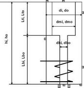
Weather data of Copenhagen, Denmark from Meteonorm is used. The heat storage volume is 300 l and the auxiliary volume in the heat storage is 150 l. The auxiliary heater inlet and outlet relative height is 1 and 0.5 for both tanks. The relative height of the space heating inlet and outlet is 0.2 and 0.8 for the tank-in-tank system. Both bikini and tank-in-tank dimensions are shown in Fig. 2a and Fig. 2b. For the tank-in-tank systems, seven different models are considered. Model 1-4 are for tanks with a 120 litre DHW tank and Model 5-7 are for tanks with a 160 litre DHW tank with different heights and diameters of the DHW tank.
The heat exchange capacity rate of both top and bottom mantle is kept constant as 200 W/m2.K for the bikini tank [4]. In tank-in-tank system, the heat transfer coefficient between the DHW tank and the outer tank is assumed to be 120 W/m2.K [6]. The heat exchange capacity rate for the internal heat exchanger spiral in the solar collector loop is 50 W/K. m2 collector area. The tank relative height is 0 at the bottom of the tank and 1 at the top of the tank.
|
Model |
і |
2 |
3 |
4 |
5 |
6 |
7 |
|
Aux volume |m3l |
0.15 |
0.15 |
0.15 |
0.15 |
0.15 |
0.15 |
0.15 |
|
Top volume of DHW tank |m3] |
0.05 |
0.093 |
0.065 |
0.065 |
0.0616 |
0.115 |
0.153 |
|
Bottom volume of DHW tank [m3l |
0.07 |
0.027 |
0.055 |
0.055 |
0.0984 |
0.045 |
0.007 |
|
Aux volume of DHW tank [m3] |
0.0725 |
0.093 |
0.0619 |
0.065 |
0.0928 |
0.115 |
0.115 |
|
di [ml |
0.46 |
0.46 |
0.46 |
0.46 |
0.46 |
0.46 |
0.46 |
|
do [m] |
0.466 |
0.466 |
0.466 |
0.466 |
0.466 |
0.466 |
0.466 |
|
hi [ml |
1.828 |
1.828 |
1.828 |
1.828 |
1.828 |
1.828 |
1.828 |
|
ho [ml |
1.834 |
1.834 |
1.834 |
1.834 |
1.834 |
1.834 |
1.834 |
|
dmi [m] |
0.36 |
0.36 |
0.3 |
0.3 |
0.4 |
0.4 |
0.4 |
|
dmo [ml |
0.366 |
0.366 |
0.306 |
0.306 |
0.406 |
0.406 |
0.406 |
|
Lti [ml |
0.486 |
0.911 |
0.486 |
0.911 |
0.486 |
0.911 |
1.216 |
|
Lto [ml |
0.49 |
0.915 |
0.49 |
0.915 |
0.49 |
0.915 |
1.22 |
|
Lbi [ml |
1.336 |
0.911 |
1.336 |
0.911 |
1.336 |
0.911 |
0.606 |
|
Lbo [ml |
1.34 |
0.915 |
1.34 |
0.915 |
1.34 |
0.915 |
0.61 |
|
dbi [ml |
0.26 |
0.194 |
0.284 |
0.28 |
0.306 |
0.246 |
0.121 |
|
dbo [ml |
0.266 |
0.2 |
0.29 |
0.286 |
0.312 |
0.252 |
0.127 |
|
Qloss [W/Kl |
2.55 |
2.55 |
2.55 |
2.55 |
2.55 |
2.55 |
2.55 |
|
Effective thermal conductivity in store [W/mKl |
3.302 |
3.302 |
3.105 |
3.105 |
3.433 |
3.433 |
3.433 |
 |
Fig. 2.a. Schematic sketch of the tank-in-tank store and dimensions for store variations
![image111 Подпись: H/D 2 3 4 di |m| 0.575 0.503 0.457 do |m] 0.582 0.509 0.463 hi m] 1.152 1.509 1.828 ho m| 1.158 1.515 1.834 dmi |m| 0.598 0.525 0.479 dmo m| 0.604 0.531 0.485 Is |m| 0.019 0.025 0.030 Lti m| 0.532 0.609 0.670 Lto m| 0.536 0.613 0.674 Lbi m| 0.543 0.621 0.683 Lbo m| 0.547 0.625 0.687 Itm m| 0.030 0.221 0.406 Qloss rW/K| 2.43 2.47 2.55 Effective thermal conductivity W/mK| 2.89 3.19 3.43](/img/1155/image111_1.gif) |
Fig. 2.b. Schematic sketch of the bikini tank and dimensions for store variations
 |
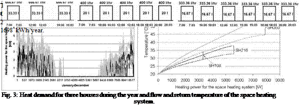
For simulation of the bikini tank and tank-in-tank solar combisystem, the non-standard component multiport store-model, Type 340, is used [7]. Three different houses with space heating demands of 5000 kWh/year (SH108), 9500 kWh/year (SH216) and 16000 kWh/year (SH360) are used for the simulations. The house area is 150 m2 Fig. 3 shows the heat demand throughout the year (left) for the houses and the flow and the return temperature of the space heating system (right).
|