Как выбрать гостиницу для кошек
14 декабря, 2021
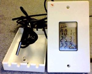
This solar controller potentially allows most types of pumped solar thermal system to become zero carbon. As used with Solartwin, upstream of the controller is a PV panel and downstream of it is a pump with a brushless DC motor. The controller will provide differential pump control plus additional functionality. Energy is stored for the processor and display at night but not for the pump, although this can be added as an option. The controller will operate DC pumps up to 25W and 22V. On the Solartwin solar thermal system we use a 12V DC brushless DC motor on a diaphragm pump with an 18 Cell Crystalline PV.
|
|
|
Fig. 1. Simplified solar water heating from Solartwin |
The design of the controller provides the end user with an attractive housing displaying temperatures, operation display and 5 cables: 2 for power and 3 sensors. The consumer is provided with onboard customisable aspects of program including:
• temperature differentials
• pump overrun time
• choice of 3 overheat options: pump on, off and differential.
The overall design is user friendly, and suitable for DIY solar heating panels for home use, sensor cables are colour coded for example.
 Fig. 2. The Solartwin zero carbon solar powered solar controller
When the system is used with a non Solartwin solar thermal system there may be small adjustments to be made on the temperature differentials when solar water heating incorporates a long pipe run (this is not as important with the Solartwin system because Solartwin utilises low volume flexible microbore silicone rubber piping rather than the larger copper pipes of traditional solar thermal). The following table displays the suggested adjustments.
|
TOTAL length (i. e. there and back added together) of unheated pipes (e. g. in lofts and on roofs PLUS HALF the length of heated pipes (e. g. in the airing cupboard and in heated rooms) |
Suggested pump overrun time setting in seconds |
Suggested start difference (over the bottom of cylinder temperature) in degrees C |
Suggested stop difference (over the bottom of cylinder temperature) in degrees C |
|
up to 10m |
30-90 sec |
4C |
2C |
|
10.1 to 15m |
120 sec |
6C |
3C |
|
15.1 to 20m |
180 sec |
8C |
4C |
|
20.1 to 25m |
240 sec |
10C |
5C |
|
25.1 to 30m |
300 sec |
12C |
6C |
|
Table 2. Temperature differential adjustment for longer pipe runs. |