Как выбрать гостиницу для кошек
14 декабря, 2021
For a better representation, only 4 cells have been selected to be interconnected. The undertaken experiments were the following:
 |
 |
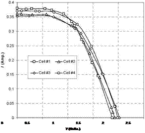
After settling the same illumination level in each cell lamp, individual cells characteristic curve was generated by potentiometer method to evaluate the observed differences in shape and basic cell parameters. As result (Figure 6), intrinsic mismatch phenomenon became evident, showing this set of 4 cells a maximum difference in short circuit current of 30 mA and 0,14 Volts in open circuit voltage (average mismatch 2,5 %)
Fig 6. Schematic arrangement for individual cell curves generation and results for 4 selected cells
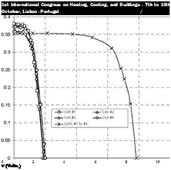
The interconnection modes here considered were a 4 cell series combination (4s) and a 2 combinations of 2 series cell junction parallel combination (2s-2p). By the potentiometer method, curves for the reference illumination level in all the cells were again obtained, in this case, for each complete generator. Table 1 and Figure 7 summarizes the obtained results.
|
Table 1. Obtained basic parameters for individual cells and combinations.
|
 |
 |
Fig. 7 Characteristic curve for 4s (left) and 2s-2p (right) interconnections
Among other results, as the current/voltage addition laws verification, it must be highlighted how the worst mismatched cell in the series interconnection (#3) determines the short circuit current of the whole generator, as expected according theoretical basis.
To study the mismatching due to partial shadowing of interconnected elements in the PV generator, the above 4s cells configuration has been selected. Shadowing of one of the series cells has been provoked by lowering the electrical feed to the lamp of one of the cells (Figure 8).
©
Fig. 8 Experimental arrangement for the study of mismatch effect provoked by partial generator shadowing
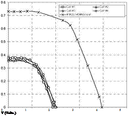
In this situation, potentiometer was used to draw corresponding load curves either for the complete mismatched generator and the shadowed cell. Figure 9 includes the obtained results as well as the corresponding curve for the no partially shadowed 4 cells series combination.
As result, in short circuit conditions, mismatched 4 cells generator is clearly affected by the lower current yield of shadowed cell, which determines the maximum current of the whole set, whereas open circuit voltage maintains its value. In this case, the reduction in generators parameters reach up to 35 % because mismatch degree has a higher value as usual in externally caused cells unbalance.
|
1st International Congress on Heating, Cooling, and Buildings — 7th to 10th October, Lisbon — Portugal /
Fig. 9 Obtained curve for partially shadowed generator and for mismatched cell |
Regarding the electrical characteristics of mismatched cell under this situation, Figure 9 also clearly show how this cell is affected by a reverse biased current coming from the rest of the cells generator. The used illumination levels and cell number in this experiment have been set to preserve mismatched cell integrity.
3. Conclusions
This work describes an experimental arrangement developed at UAL aimed to serve as educational tool in courses and lessons on PV generators performance and the study of specific effects as the mismatch loses in modules or arrays. All the components of the device are low cost and easily available in most of the university laboratories and the results of the experiences curves can be immediately related to the theory. As future improvements, cells temperature follow-up, specific light source use and safety diodes study will be considered.
References
[1] Kaushika N. D. and A. K. Rai, Energy 32-5 (2007) 755-759.
[2] Alonso-Garcia M. C., J. M. Ruiz and F. Chenlo, Solar Energy Materials and Solar Cells 90-3 (2006) 329-340.
[3] Kaushika Narendra D, Guatam Nalin K. Energy yield simulations of interconnected solar PV arrays. IEEE Trans Energy Convers 2003;18(1):127—34.
[4] Woyte A., J. Nijs and R. Belmans; Solar Energy 74-3 (2003) 213-217.
[5] Osterwald C. R. (2003) Standards, Calibration and Testing of PV Modules and Solar Cells, in Markvart T. and L. Castaner (Eds.) Practical Handbook of Photovoltaics: Fundamentals and Applications. pp. 793-856. Elsevier, Oxford.