Как выбрать гостиницу для кошек
14 декабря, 2021
 |
In general terms, given a temperature and irradiance values, the load curve of a conventional solar cell can be represented by a classical parametric model (Figure 2) in which it can be distinguished 3 operation zones in regard to the load nature. As shown, cells being operated in reverse bias mode can suffer structural damage. Mismatch appears when the electrical parameters of one or several solar cells are significantly altered from those of the remaining devices and being altered the resulting curves shown in Figure 1. The alteration of a cell can consist, as advanced, of slight parameters modification due to the tolerance in manufacturing process or a change in its operating conditions in regard to the rest because the blocking of radiation impinging the cell surface.
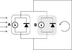
For simplicity, we will restrict the description of the influence of mismatched parts to a circuit constituted by 2 single cells, A and B (Figures 3 and 4), being the cause of the unbalanced behavior the shading of cell B.
 |
For a series interconnection, Figure 3 (right) shows how open circuit conditions for A+B generator are no highly affected by mismatching of cell B. However, as the current through the two cells must be the same, the overall current from the combination cannot exceed that of the poor cell. Therefore, the current from the combination cannot exceed the short-circuit current of the poor cell. At low voltages where this condition is likely to occur, the extra current-generating capability of the good cells is not dissipated in each individual cell (as would normally occur at short circuit), but instead is dissipated in the poor cell. An easy method of calculating the combined short circuit current of series connected mismatched cells is to consider that the current at the point of intersection represents the short circuit current of the series combination (VA+VB=0).
 |
 |
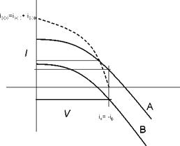
For parallel connected cells, at low voltages, there is no real problem with mismatch as the currents just add and the total current is always higher than the individual cell currents. However, the resulting open circuit conditions are highly affected because the addition of mismatched cell B reduces the open circuit of A+B generator to a lower value in regard to the original one. A simple method to calculate the resulting open circuit voltage in this situation is to consider according individual cells curves that the above will occur when iA + iB = 0,as shown in Figure 4 (right).
Fig. 4 Mismatching in parallel connected cells