Как выбрать гостиницу для кошек
14 декабря, 2021
A model of the top heat thermosyphon proposed in the present study is shown in Fig.1(a), called IMT model. The system equipped with a small reservoir of water at the end of the condenser as shown in the figure. The condenser located on the top of the system is consisted of two tubes soldered together. The flow of the mixture of the liquid and vapor in the upper tube is cooled by the lower tube in which the liquid from the cooler flows so that the vapor in the upper tube is condensed. When the volume of the vapor is increased, the total volume of the vapor and the liquid expands. It is aimed to have reservoir for storing the extra liquid at the top. The loop tubes are made from chopper. The inside and outside diameters of loop tubes are 8mm and 9.5mm, respectively, except the tubes of evaporator which have inside and outside diameters of 11mm and 12.7mm, respectively. The length of the evaporator is 620mm. The length of tube of the condenser is 1800mm. The length of the coil dipped in the cooler or water batch controller as heat exchanger is 1200mm. The length between the center of the evaporator and the center of the cooler is 1140mm. The heat input of evaporator is supplied by two ribbon heaters wich consume 250W for one heater. The power of two ribbon heaters are varied by resistors from 0 to 500W. The dimension of thickness, width, and lenght are 1mm, 20mm, and 500mm, respectively.
As shown in Fig.1(b), some temperature measurements are located around the body of the tubes. T0 is to measure the inlet temperature to the evaporator. T1 to T6 are to measure the temperature inside the
 |
 |
evaporator. T7 is to measure the exit temperature of water from the evaporator. T8 to T13 are to measure the temperature in the heat exchanger (condenser). TJ4 and TJ5 are to measure the inlet and outlet temperature of heat exchanger (condenser). TJ6 is to measure the temperature inside the top heat storage. T17 is to measure the temperature inside the water bacth controller (cooler). TJ8 is to measure the inlet temperature to the water batch controller. T19 is to measure the outlet temperature from the heat exchanger and the top heat storage. T2o is to measure the outlet temperature from the water batch controller. T21 is to measure the outlet temperature from the flow meter. To investigate more details the performance of this IMT model, some parameters are varied. Heat input are varied with 100, 200, and 300W, comparing with the previous report were 200 and 400W [5]. The inclination angle between the evaporator and the top heat storage are varied with 00, 50, and 100. The remained water in the top heat storage are varied with 93%, 77%, and 61%. The water batch controller keeps the temperature at 400C and one experiment takes 90 minutes and the data is collected for every 30 seconds.
a. IMT Model — experimental set up b. Temperature measurement position
Fig.1. Experimental set up and temperature measurement position for IMT Model
Table 1 shows the 14 experiments with varied parameters. There are 6 experiments for heat input 100W, which are Exp.1 (100W, 00, 93%), Exp.3 (100W, 50, 93%), Exp.6 (100W, 50, 77%), Exp.8 (100W, 100, 93%), Exp.10 (100W, 100, 77%). Exp.13 (100W, 100, 61%). There are 4 experiments for heat input 200W, which are Exp.4 (200W, 50, 93%), Exp.7 (200W, 50, 77%), Exp.11 (200W, 100, 77%), Exp.14 (200W, 100, 61%). There are 4 experiments for heat input 300W, which are Exp.2 (300W, 00, 93%), Exp.5 (300W, 50, 93%), Exp.9 (300W, 100, 93%), Exp.12 (300W, 100, 77%).
10th October, Lisbon — Portugal r
|
Heat Input |
The Inclination Angle and The Remained Water in the Top heat storage |
||||||||
|
00 |
50 |
10° |
|||||||
|
93% |
77% |
61% |
93% |
77% |
61% |
93% |
77% |
61% |
|
|
100W |
Exp.1 |
Exp.3 |
Exp.6 |
Exp. 8 |
Exp. 10 |
Exp.13 |
|||
|
200W |
Exp. 4 |
Exp. 7 |
Exp. 11 |
Exp. 14 |
|||||
|
300W |
Exp.2 |
Exp. 5 |
— |
— |
Exp. 9 |
Exp. 12 |
— |
|
Table 1. The experiment with some varied parameters |
2. Result and Discussion
 |
 |
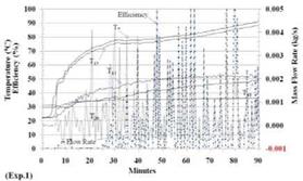
The performance of these experiments can be evaluate by two factors, efficiency and steady circulation. Fig.2 shows the experimental results for heat input 100W with variation of the inclination angle and the remained water in the top heat storage. There are six experiments have been done for heat input of 100W. There are two experiments which gave the higher efficiency and a steady circulation. They are Exp.3 (100W, 50, 93%) and Exp.6 (100W, 50, 77%). The other 4 experiments which gave the low efficiency and unsteady circulation are Exp.1 (100W, 00, 93%), Exp. 10 (100W, 100, 77%) and Exp.13 (100W, 100, 61%).
Fig.2. Variation of temperatures, mass flow rate, and efficiency for heat input of 100W
 |
 |
Fig.3 shows the experimental results for heat input of 200W with variation of the inclination angle and the remained water in the top heat storage. There are 4 experiments have been done for heat input of 200W. Exp.4 (200W, 50, 93%) and Exp.7 (200W, 50, 77%) shows a good performance with higher efficiency and steady circulation but the performance of Exp.11 (200W, 100, 77%) and Exp.14 (200W, 100, 61%) are very poor, means that lower efficiency and unsteady circulation.
Fig.3. Variation of temperatures, mass flow rate, and efficiency for heat input of 200W
 |
 |
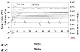
Fig.4 shows the experimental results for heat input 300W with variation of the inclination angle and the remained water in the top heat storage. There are 4 experiments have been done for heat input of 300W. The performance of Exp.2 (300W, 00, 93%) and Exp.5 (300W, 50, 93%) are very poor, means that lower efficiency and unsteady circulation. Exp.9 (300W, 100, 99%) and Exp.12 (300W, 100, 77%) show good performance with higher efficiency and steady circulation.
Fig.4. Variation of temperatures, mass flow rate, and efficiency for heat input of 300W
|
Table 2. Summary of the experiments
|
Table 2 shows the summary of the experiments. The highest efficiency for heat input 100W is achieved by Exp.6 (68%) and the lowest efficiency is achieved by Exp.13 (-0.3%). For heat input 200W, the highest efficiency is achieved by Exp.7 (59%) and the lowest efficiency is achieved by Exp.11 (33%). The highest efficiency for heat input 300W is achieved by Exp.12 (69%) and the lowest efficiency is achieved by Exp.2 (41%). The highest overall efficiency for these experiments is achieved by Exp.12 (69%).
The performance of thermosyphon with heat source near the top and heat sink at the bottom was studied by varying the operation parameters of heat input, inclination angle, and the remained water in the hot water storage. Result shows that the inclination angle and the remained water in the top heat storage are the important parameters which can influence the performance of thermosyphon.
The support of “High-Tech Research Centre Project for Private Universities: matching fund subsidy from MEXT, 2007-2011” for this research is appreciated.
[1] F. F. Jebrail, M. J. Andrews, “Performance of A Heat Pipe Thermosyphon Radiator",
International Journal of Energy Research, Vol. 21, 101-112 (1997)
[2] G. L. Morrison, “Solar Water Heating”, Solar Energy edited by J. Gordon, 2001, International Solar Energy Society, p.223-289
[3] R. Khodabandeh, “Heat Transfer in The Evaporator of An Advance Two-Phase Thermosyphon Loop”, International Journal of Refrigeration 28 (2005) 190-202
[4] S. I. Haider, Y. K. Joshi, W. Nakayama, “A Natural Circulation Model of The Closed Loop, Two Phase Thermosyphon for Electronics Cooling”, Journal of Heat Transfer — October 2002, Vol. 124 / 883
[5] S. Ito, N. Miura, K. Tateishi, “Studies of A Thermosyphon System with A Heat Source Near The Top and Heat Sink at The Bottom”, Solar World Congress, Beijing, September, 2007
[6] S. Ippohshi, S. Tabara, K. Motomatu, A. Mutoh, H. Imura, “Development of A Top-Heat Mode Loop Thermosyphon”, The 6th ASME-JSME Thermal Engineering Join Conference, March 1620, 2003
[7] Y. Maydanik, “Loop Heat Pipes-Highly Efficient Heat Transfer Devices for Systems of Sun Heat Supply”, Proceedings 1 of Eurosun 2004 Conference, 2004, p.470-47