Как выбрать гостиницу для кошек
14 декабря, 2021
In this heat and mass transfer prototype, the desiccant solution and the air stream is brought into contact with each other in a cross flow configuration. The regenerator consists of a stack of polycarbonate (PC) twin wall plates. Each plate has an internal heating water circuit. The plates are covered with a wick fibre to facilitate intimate contact between the liquid desiccant and air. This is done to increase the exposure time over the plates and thereby enhance the desired mass transfer and heat exchange. The general design is shown in the left part of Fig. 2.
The advancement of the distribution system consists of:
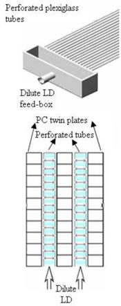
• a separation between the liquid desiccant distributor and the contact area between air and desiccant. The LiCl solution is distributed over the textile separately in an advance stage i. e. before coming in contact with the air stream. A separator is used to split the generator into two chambers. In the upper small chamber LiCl throttled through perforated plexiglass tubes, completely diffused through the textile fibres and trickles down to come in contact with the horizontal air stream in the lower large chamber. This separator will prevent LiCl particles to drift into the air stream, resulting in a zero carryover regenerator.
• the employment of promising fibres, a new natural man made fibre produced from wood pulp. This fiber can absorb 50% more moisture than cotton did, it has a lower sorption index than cotton, which means higher transport speed of the liquid.
• the employment of perforated plastic tubes with different tested throttling-points diameters.
The LD distributor in this design uses a plurality of parallel plexiglass tubes to horizontally distribute the LD over the wick. The parallel tubes extend outwardly from openings in the lower edge of one of the sides of a LD feed box and are closed from the free end. The tubes penetrate the PC plates horizontally and deliver the desiccant solution over the coated plates at a number of equally spaced-apart locations (discharge-holes). The distributor is shown on the right part of Fig.
2.
The discharge holes are preferably formed on the plexiglass tubes by using a CNC machine to make the fine drip points with high precision. The size and number of the discharge holes are selected to provide the desired liquid flow. The throttling-point density determines the flow into the wick material covering the PC twin-wall plates. Likewise, the distance between the discharge — holes is selected to accommodate the desired LD flow rate with the maximum even distribution.
 |
|
 |
|
The regenerator consists of an upper and a lower hot water-feeder box. Each water feeder box consists of four equal chambers separated by baffles. Hot water will pass through the internal passages of the PC twin-wall plate in a 3-loop serpentine path. It will enter the first chamber from a primary opening in the upper wall of the chamber, and it collides with a liquid spreading surface that faces the internal PC passages. The spreading surface will also disrupt the downward flow of water and will direct it equally to the channels.
Fig. 2. Exploded view of generator design along with the illustration of flow directions of heating water, LD and air (upper left), an isometric enlargement of the LD distribution system and a top-view of how the glass tubes penetrate the polycarbonate twin-plates (upper right).