Как выбрать гостиницу для кошек
14 декабря, 2021
M. Zetzsche1), T. Koller1), H. Mtiller-Steinhagen^ 2)
1 University of Stuttgart, Institute of Thermodynamics and Thermal Engineering
Pfaffenwaldring 6, D-70550 Stuttgart, Germany
Tel.: 0049-711-685-63230, Fax: 0049-711-685-63503
E-Mail: zetzsche@itw. uni-stuttgart. de
2) Institute of Technical Thermodynamics, German Aerospace Center (DLR)
Abstract
The Institute for Thermodynamics and Thermal Engineering of the University of Stuttgart (Germany) is developing a solar-driven cooling system based on an ammonia/water absorption chiller. In addition to the cooling engine itself, a concept for the cooling of buildings has been realized. Essential parts of this concept are the building with chilled ceilings, an ice storage and the absorption chiller which works with a dry cooling system. Following a period of intensive testing and analysis of the performance, the chiller will now be operated under practical conditions. Therefore, five rooms of the department’s building have been equipped with chilled ceilings and are connected to the solar-driven chiller unit.
In the present paper, operational details of the chiller and the general cooling concept will be presented. Additionally, the combination of the chiller with the dry cooling system, the solar collectors and the ice storage will be discussed. Charging and discharging of the ice storage play an important role for covering the cooling load at any time. All components are controlled with an SPS (stored program control) control unit. Measurement data such cooling power, thermal comfort in the rooms, COP of the absorption chiller with boundary conditions like cooling temperatures and solar radiation are presented. The quality of the supply with cooling energy is part of this paper.
Keywords: solar cooling, absorption chiller, ammonia water, ice storage, chilled ceiling
1. Introduction
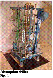
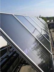
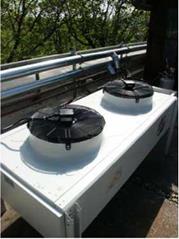
The ITW-absorption chiller has a cooling capacity of 10 kW at standard conditions (14 °C chilled water outlet, 27 °C cooling water inlet, 100 °C hot water inlet, COP 0,72) [1]. The working fluids are ammonia and water. For heat rejection a dry cooling tower is used. As heat source flat plate
 |
|
 |
 |
collectors with a high efficiency are applied. The main components are shown in the following figures.
Flat plate collector (32 m2) Dry cooling tower Components of ITW-solar cooling system
Four offices and one meeting room of the department’s building are equipped with chilled ceilings. The total area of all rooms amounts to 115 m2. In each office 3 persons are working. The offices are usually occupied from 8 a. m. to 17 p. m.. The occupation of the meeting room is variable. During the measurements the meeting room was not occupied, nevertheless it was cooled. The orientation of the windows in the rooms is east and the solar collectors are orientated to the south. In addition to the chiller an ice storage is installed. This storage was developed parallel to the development of the ammonia/water chiller. It was measured and tested with several heat exchangers [2]. The storage tank has a volume of 500 litres and an amount of ice of 300 kg can be produced. This corresponds to a cooling capacity of 35 kWh.
The ice storage is charged by the chiller and can be used as a back-up system or an extension to cool the rooms.
Figure 2 shows a schematic lay-out of the piping of the components.
Two heat-exchangers are installed to transfer the cooling energy from the chiller or from the ice storage to the rooms. The ice storage is discharged by external melting of the ice. This means that the water in the ice-storage is directly used in the heat exchanger.
In every room the complete ceiling is covered with metal cooling panels. When using chilled ceilings it is important to control the inlet water temperature into the rooms. Condensation of the ambient air on the chilled ceiling must be avoided. Additional to the control of the forerun
temperature, a sensor for relative humidity is installed in every room. When the dew point is reached, the sensor provides a signal to the controller and the flow through the chilled ceiling of this particular room is stopped.
|
|
Other than the ice storage, no other thermal storage facilities are installed. One special feature of the ITW chiller is that the heating temperature has not to be controlled. The heating temperature depends on the thermodynamic equilibrium of the solution in the generator. The evaporation in the generator starts when a certain temperature level, which depends on the concentration of the ammonia in solution, is reached. If the required temperature level is not available, the outlet temperature of the generator is almost equal to the inlet temperature. Hence, the collector cycle is heated up until the required temperature level is available. Then the absorption cycle starts to work.
The main influence on the required temperature level is the concentration of ammonia in the strong solution. This concentration depends on the cooling temperature of the absorber.
The chiller unit is controlled by an SPS (Stored Program Control). The SPS unit switches all of the pumps and the dry cooling tower on and off. Internal valves are regulated in such a way that the COP is always at maximum. Of course, the maximum COP depends on the boundary conditions when the chiller is running. These boundary conditions, like hot water temperature, recooling temperature and cold water temperature, are taken into account for the control process. When COP is an maximum the cooling power will be also at the maximum (1).
The available cooling power must be used as efficient as possible, either to cool the rooms or to store the cold energy in the ice storage. Therefore several control strategies have been developed. The control of the system is adapted to the climatic conditions and the cooling load in the rooms. It is intended to cover with this system the cooling demand all the time when the rooms are occupied. Therefore the system may be operated in five different states:
(1) Direct cooling of the rooms. Cooling energy is transferred with heat exchanger no. 1.
(2) Producing ice, if no room cooling is needed (e. g. on weekends).
(3) Cooling the rooms and producing ice at the same time. The storage is charged and discharged simultaneously. The cooling energy is transferred with heat exchanger no.2. In this case the cooling capacity of the rooms has to be lower than the cooling performance of the chiller when producing ice at 0°C to -10°C.
(4) Discharging the ice storage when the chiller is out of operation (e. g. in the morning, at night, etc.)
(5) Supporting the performance of the chiller by simultaneously discharging the ice storage. In this case, peak demands can be covered or cooling energy can be supplied when the sky is cloudy and the solar gains are low.
In every room a sensor for air temperature and relative humidity has been installed to evaluate the thermal comfort. Furthermore temperature sensors (thermocouples) are fitted to every inlet and outlet of heat exchanger no. 1 and no. 2. The flow through these heat exchangers is measured as
well as in the chilled ceiling circuit. The measurements for the operational states (1) and (2) are presented in the following chapters.