Как выбрать гостиницу для кошек
14 декабря, 2021
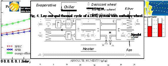
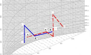
Another interesting alternative to the standard DEC system is shown in Fig. 4. In this configuration, dehumidification is performed in two different stages; the first stage is carried out by means of an enthalpy wheel, which is similar to the recovery wheel, but in which latent heat can also be exchanged, thanks to the adsorbent materials which cover the rotor surface. Thanks to the enthalpy wheel, a certain amount of water vapour is transferred from the process air to the exhaust air, thus avoiding the use of a pre-cooling coil; but the most important consequence is the need of a lower regeneration temperature, which in this case reduces to 61 °C, given the same inlet conditions for the supply air (point I in Fig. 4). This means that both the cooling and the heating power required by the air-handling unit reduce, allowing important improvements on energy savings and exergy performance, as shown in Fig. 5, where the comparison is made with the standard DEC system working with Treg = 70°C.
 |
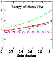
 Fig. 5. Improvements due to the adoption of an enthalpy wheel
The most relevant results refer to the exergy efficiency, and are mainly due to the consistent reduction of the cooling power, which is produced through the use of electric energy, characterized by very high exergy content. The adoption of this solution also emphasizes the advantage of using solar energy to assist regeneration, as the performance improvement gets higher for high solar fractions.
As shown in the previous paragraphs, it is possible to improve the energy and exergy performance of a standard DEC system by adopting some additional components which allow relevant energy recovery.
 |
 |
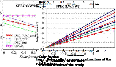
Fig.6 summarizes the most important results, and underlines the great advantage of using the solution with an enthalpy recovery wheel. For a right interpretation of the results it is necessary to look at Fig. 7, as a certain solar fraction corresponds to different collecting surface according to the system which is considered; indeed, the entity of the thermal power required by the heating coil depends on the plant scheme. This is an aspect which can not be neglected, especially if the first and second law results of this study must be translated in economic figures. In terms of collecting surface, the results are shown in Fig. 7; they refer to vacuum tube solar collectors and an overall irradiation as high as 800 W/m2.
[1] G. Evola, L. Marietta, F. Sicurella, Energy and Environmental Performance of Solar-assisted Desiccant Ventilation Units: a Life-cycle Perspective, CLIMAMED International Conference, Genoa, 2007.
[2] Daou K., Wang R. Z., Xia Z. Z., Desiccant cooling air conditioning: a review. Renewable & Sustainable Energy Reviews 10 (2006), pp. 55-77.
[3] Mazzei P., Minichiello F., Palma D. HVAC dehumidification systems for thermal comfort: a critical review. Applied Thermal Engineering 25 (2005), pp. 677-707.
[4] G. Evola, L. Marietta, F. Sicurella, Second law analysis of solar-assisted desiccant open cycles: a comparative analysis, 2nd International Conference on Solar Air-conditioning, Tarragona, 2007
[5] A. Bejan, Advanced Engineering Thermodynamics. New York: John Wiley & Sons, 1988.
[6] W. J. Wepfer, R. A. Gaggioli, E. F. Obert. Proper evaluation of available energy for HVAC. Ashrae Transactions 85 (1979), pp. 214-230.