Как выбрать гостиницу для кошек
14 декабря, 2021
The energy performance of the solar system varying the collectors surface and the storage tank volume was evaluated. The collectors used for the simulation are already in existence and heat a water-glycol mix in order to reach temperatures of up to 120 °C.
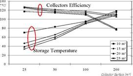
The capturing surface was made to vary between 25 m2 and 200 m2 and the storage volumes from 10 m3 to 25 m3. These values result as being large for the inlet temperatures of the radiant ceiling during winter, but are necessary in order to guarantee regular functioning of the absorption machine during summer. In Figure 3 the average seasonal temperature trend of the tank and the average seasonal yield of the collectors varying the capturing surface and storage volume is represented. High temperature within the tank penalises the performance of the collectors. Furthermore, given that the required inlet temperatures of radiant ceilings are 30^40 °C, the mixing system (1) operates for part of the time with high recirculating flow rates and low flow rates taken from the tank. The rapid decrease of the efficiency of the collectors which is recorded for an capturing surface area of 200 m2 and for a storage volume of 10 m3 and 15 m3 is linked to the
reaching of the maximum temperature and the operation of the safety valve of the primary circuit of Figure 1 which interrupts the accumulation of thermal energy in the tank. The reaching of high temperatures gives rise above all to limited global yields of the solar system which do not vary with the volume of the storage tank.
In Figure 4 the trend of the energy captured by the solar collectors , of the energy provided by the auxiliary system and of the energy extracted from the storage tank, varying the collectors surface and storage volume is shown. The seasonal thermal energy provided by the auxiliary system and the energy extracted from the tank are practically constant with the storage volume, and their sum represents the seasonal requirement of thermal energy of the building which appears to be equal to around 35000 kWh. From Figure 4 it is possible to observe the minor energy captured by the solar collectors upon reaching the maximum temperature in the tank.


![]() 80000 70000 ^ 60000 50000 40000 30000 20000 10000 0
80000 70000 ^ 60000 50000 40000 30000 20000 10000 0
0 50 100 150 200 250
Collectors Surface [m2]
Fig. 4. Seasonal energy captured by the collectors, energy provided by the auxiliary system and energy extracted from the storage tank varying the capturing surface and storage volume
 |
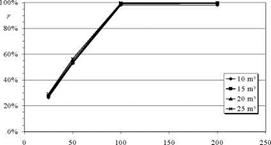
The requirement energy fraction obtained from the solar source, represented in Figure 5, assumes values that vary from 26% until almost 100%; a rapid increase is highlighted moving from an capturing surface of 25 m2 to an capturing surface of 100 m2, while it remains almost constant with the storage volume and for capturing surfaces greater than 100 m2.
Collectors Surface [m2]
Fig. 5. Solar fraction trend varying the capturing surface and storage volume