Как выбрать гостиницу для кошек
14 декабря, 2021
A thermal/solar panel unit was designed and connected to a refrigerator unit, as shown in Figure 2. In this project the electric source for a bubble pump was replaced by the solar thermal system. The system consisted of two parts; the cooling unit and a deep freezer that used an ammonia refrigerant for cooling. The other part is the solar thermal system. The main function of the system was to heat the water by utilizing solar energy.
|
Figure 2: A thermal-solar panel system used in the present work |
The design of the purchased solar unit was altered in order to increase the heat absorbed by the system. The straight panel pipes (Figure 3), that carry the water used to collect heat from the sun, were replaced with a more efficient design. A copper piping system, in the form of a spiral (Figure 3), was designed to transport water around the system. The original piping system had less surface area and thus less heat absorption capability. The newly designed spiral copper pipe had a length of 30m, and was painted black to give it the black body characteristics. The length of the pipe was increased in order to increase the residence time of water in the pipe, and hence can absorb more heat from the sun. The heater was removed and water hoses were connected to the bubble pump.
 |
 |
Figure 3a: Old piping design Figure 3b: New designed spiral piping system
 |
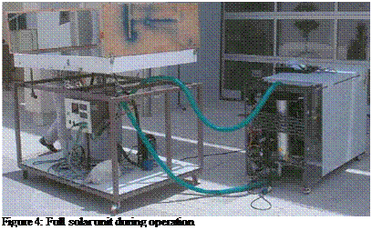
During operation, hot water runs through the spiral and gets heated by the solar energy (the maximum water temperature obtained by the new design was 80oC). The resulting heat from the water was then used to heat the NH3-H2O mixture. Welding skills acquired from a previous welding course were used to weld and braze the pipe. The copper pipe was then connected to pipes that were connected to the bubble pump and water tank. Thermocouples were installed in several locations, with the most important ones being those measuring the inlet and outlet pipe temperatures. In order to increase the heat absorption efficiency of the system, four mirrors were also installed along each side of the solar panel. The angle of the mirrors can be adjusted such that a maximum amount of heat, at any time of day, can be absorbed. Figure 4 shows a photograph of the thermal solar system during operation.
|
Figure 5: Combined system consisting of thermal unit and photovoltaic cell |
The newly designed system was tested during the hot summer months, and it showed that it is possible to absorb heat from the sun, heat the running water and cool the refrigeration system by more than 20oC.
The minimum temperature achieved by the present system design was +5oC. However, since the desired refrigeration temperature is < 0oC degrees, some modifications thought to be needed to possibly achieve the target temperature. Since the system showed a good potential in not only absorbing heat, but also cooling down a deep freezer by about 20oC, the next step of the project was to combine the present solar system with a photovoltaic system. The function of the photovoltaic is to operate the 50 Watt pump and store electrical energy for night use. A photovoltaic unit was purchased. The system has a capacity of 450-Watt and consists of three photovoltaic cells (150 Watt each), AC-DC inverter, and a 12-volt converter. These specifications are expected to operate the system for 4-6 hours at a maximum capacity. Unfortunately, the purchased photovoltaic cells never made through customs, and after a long time waiting, the idea of using photovoltaic cells had to be abandoned. The encouraging results obtained from the refrigeration system enticed us to explore using the system to cooling the space around it.