Как выбрать гостиницу для кошек
14 декабря, 2021
From the test sequences obtained for QD test method, test periods according to SS test method conditions were selected and the parameters of efficiency curve determined (equation (3)). The values determined are listed in Table 2.
|
Table 2: Parameters of efficiency curve according to SS test method
|
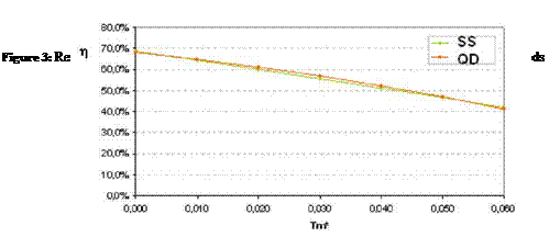
Comparison of results between the QD and SS methods is presented in the form of an efficiency curve with respect to Tm* = (tm-ta)/G*, where G* is the global irradiance incident on the collector. The following values were considered:
G* = 1000 W/ m2; Gd = 150 W/ m2; 0: = 15°
according to the standard’s recommendations for the presentation of results.
 |
The above figure shows good agreement between the two test methods for the flat plate collector tested.
An evacuated tubular collector was also tested. It was a double glazed tubular collector and had as heat transfer device a heat pipe.
Test sequences were obtained but the identification of characteristic parameters was not successful since further development of the MLR tool was needed due to the fact that IAM can not be characterized by equation (7) for this type of collectors.
Also a strange behaviour of the collector was detected in the test sequences, showing that, after a certain time period the collector performance was enhanced, i. e, the outlet collector temperature raised in almost step wise way after a couple of hours, showing a different behaviour between morning and afternoon. The reason for this behaviour could not be determined.
The QD test methodology was implemented at LECS. For this implementation data acquisition programme and MRL tool were developed. First results were obtained for a flat plate collector and showed good results, although a better choice of test sequences is needed in order to incorporate a better weather variability, i. e., sequences with cloudy conditions.
For test of collectors with higher optical complexity, adaptation of the MLR tool is needed. This is the case of CPC type and evacuated tubular collectors.
[1] EN 12975 (2006), Thermal solar systems and components — Solar collectors — Part 2: Test Methods, Section 6.1. and Section 6.3, European Standard.
[2] Rojas, D. et al., Thermal performance testing of flat-plate collectors, Sol. Energy (2008), doi:10.1016/j. solener.2008.02.001
[3] Carvalho, M. J., P. Kovacs, Fischer, S., Project NEGST — New Generation of Solar Thermal Systems, "WP4-D2.1.k — Resource document — Definitions and test procedure related to the incidence angle modifier”, 2006, in http://www. swt-technologie. de/WP4 D2.1 ges. pdf
[4] Horta, P., M. J. Carvalho, S. Fisher (2008), Solar thermal collector yield — experimental validation of calculations based on steady-state and quasi-dynamic test methodologies, Submitted for presentation at Eurosun2008, Lisboa.
[1] Introduction
Solar water heating (SWH) systems are not usually equipped with any fault diagnostic system (FDS). Any faults are usually identified either by regular inspection by servicing personnel or when the system is not producing appropriate quantities of hot water, which is the most frequent. Usually people forget the existence of the solar system and this is inspected only after hot water is not available, indicating some problems. This results in problematic operation of the systems for long periods of time, which reduce the effectiveness and viability of the systems. Primarily works present the possibility of on-site determination of faults [1-2]. But the drifts were of a step-by-step
[3] Du to changes in the official CEN nomenclature the previously used abbreviation ENV for the indication of a preliminary standard is now replaced by the abbreviation CEN/TS (CEN: Comite Europeen de Normalisation — European Committee for Standardisation ; TS: Technical Specification).
[4] European Committee for Electrotechnical Standardization — Comite Europeen de Normalisation Electrotechnique
[5] Duff, W. S., Winston, R., O’Gallagher, J., Henkel T. and Bergquam, J., “Five Year Novel ICPC Solar Collector Performance”, 2003 American Solar Energy Society Solar Energy Conference, Austin TX, June 2003
[6] Duff, William, Roland Winston, Joseph
[7] The CSTG — method was originally developed within an European Project by the “Complete System
Testing Group” (CSTG). Today this method is standardised in ISO 9459-2
[9] DST: Dynamic System Test. The DST-method is standardised in ISO 9459-5.
[10] The collector performance calculated from the collector parameters gained under steady state conditions is only valid for the diffuse fraction prevailing during the measurements. The usage of these results leads to an under-estimation of the collector output for diffuse fractions smaller and to an over-estimation for diffuse fractions larger, than the values predominant during the steady state measurement.
[11] ++ well developed / can be applied directly, +- further research and development, — early R&D
[12] — not automated, +- partly automated, ++ fully automated