Как выбрать гостиницу для кошек
14 декабря, 2021
4.1. Test of a flat plate collector
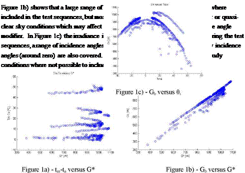
A selective flat plate collector was tested according to QD test methodology. In order to analyse the test sequences, graphs were generated according to the recommendations of the standard EN 12975-2 section 6.3. These graphs are represented in Fig. 1.a), b) and c).
 |
Analysis of the graph in Figure 1a) shows that the test was conducted within the expected working temperature range of the collector. This meets the requirement to have at least 4 fluid inlet temperatures evenly spaced in the collector’s working temperature range. One of the tests was conducted under conditions in which the collector’s mean fluid temperature stood at ± 3 K of ambient temperature, around solar noon, so as to make possible a precise determination of n0.
The parameter identification using the developed the MLR tool gave the results listed in Table 1.
|
Table 1: Parameters determined with MLR analyses
|
As already referred, the fact that not enough cloudy conditions were included in the test sequences may have induced the determination of values of b0 and Kd, which are not in agreement with the expected values for a flat plate collector.
Also the parameter c5 shows a very low value, maybe as a result of not enough transient data included in the test sequences. Although individually the parameter values are not completely in agreement with the expected values, de comparison of the power curves — measured and calculated using equation (8) and the parameters of Table 1, shows very good agreement. This is shown in Figure 2.
|
|
Figure 2 — Comparison of calculation of Q/A using the model with lab results.