Как выбрать гостиницу для кошек
14 декабря, 2021
The magnitude of the natural convection heat transfer is related to the mass flow rate of the air, which is established by the dynamic balance of two opposing effects: buoyancy and friction. Inherent to the flow inside the duct, are the pressure difference between the inlet and outlet air of the channel since the mean air temperature along the axial length of the duct in the flow direction will change (constant heat flux).
2.3 Driving Forces
It would be expected that the presence of these structural element will increase both the heat transfer rate and the hydraulic pressure loss. Under natural convection, the pressure drop due to the buoyancy forces is a result of the temperature difference between the heated surface and the column of the air in the duct. At a typical height (x) from the base corresponding to length (Lx) of the duct, the buoyancy pressure drop is given by [3].
![]() APbx = PmgPexp(Ta, x — Ta, i )Lx sin P
APbx = PmgPexp(Ta, x — Ta, i )Lx sin P
4.2. Resistance to Flow
In the absence of hydraulic losses (variable cross sections, losses through valves, orifices, elbows), the resistance to flow in the channel is resumed to the friction pressure drop (Ap) and was computed as
[10] :
APf = pghf (14)
where, the friction head loss ( h ) is given by:
L V2
duct m
2 gDh
Therefore the pressure drop is expressed as:
![]() P йиеУm
P йиеУm
2 gDh
For a given BIPVT system, the choice of the duct length (Lduc{) is determined by the dimension of the
roof and therefore any design to optimise energy and heat transfer will be determined by the duct dept. The friction factor (f) for laminar and turbulent flow were respectively evaluated as suggested by Tsuji
[11] , and Smolec [12].
![]() f = 1.906(Gr Pr)1/12
f = 1.906(Gr Pr)1/12
f = 1.368(Gr Pr)1/119
5.1. Data Analysis
 |
 |
The steady state values were recorded over a period of time. Due to measurement fluctuations in the experiment a statistical uncertainty analysis was conducted. Initial analysis of the raw data yielded the mean and standard deviation of the measurements. Assuming the measurement fit a normal Gaussian distribution, the uncertainty was then calculated with a confidence level of 95%. The error propagation method was used and the average data evaluated. Figure 6 gives the magnitude of friction losses.
Figure 7. Magnitude of pressure drop under Figure 7. Temperature distribution on top plate along
natural convection the duct length at H = 4 cm, slope angle = 44°
It can be seen from figure7, that at a specific heat flux, buoyancy forces can be neglected.
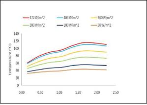
In figure 7, the temperature decrease at the entrance and at the exit is due to radiation losses. Applying a polynomial form of the 6th order to the test data, the temperature distribution as shown in figure 10 can be expressed as:
T(x) = 36.92×6 — 245.8×5 + 605.0×4 — 673.4×3 + 316.8×2 + 0.248x + 55.37
R2 = 0.99
 |
 |
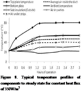
Figure 8 shows a typical temperature profile of components at steady state at a constant heat flux of 350W/m2, while illustrates the variation of the local air velocity as function of various heat fluxes.
As illustrated in figure 8, the air temperature under the wood strips Ta2, Ta4, and Ta6 (figure 2) remained lower than the air temperature in the cavities (Ta1, Ta3, Ta5, Ta7). At steady state the air in the cavities and the bottom plate have the same temperature.
As expected, the presence of the structural elements in the channel constituted an obstacle to the air flow inside the channel due to the increase in pressure drop and friction losses. Consequently, under the same constant heat flux, the reduced air flow rate in the channel due to the wood strips led to an increase in the components temperature as compared to the system without wood strips as illustrated in figure 9.
Experimental investigation of temperature distribution in a BIPV system under natural convection has been done. The results of the experiment show that the framing structure of BIPV under natural convection does not contribute to the temperature reduction of photovoltaic module cells. The temperature at the boundaries and the velocity profiles are used to create and validate CFD numerical models [13].
Acknowledgement
The current ongoing research work is supported by the Solar Building Research Network, a NSERC Strategic Research Network. A special thank to the Solar Calorimetry Laboratory at Queen’s University (Ontario) and the Department of Building, Civil, and Environmental Engineering at Concordia University (Quebec) for hosting the research work.
Symbols Definition
A Cross section area of the duct (m2) L Thickness of bottom insulation (m)
duct oms
C Specific heat at bulk mean air L Thickness of side insulation (m)
p sin s
|
7th to 10th October, Lisbon — Portugal
|
T Ambient air temperature (K)
[1] Benemann, J., Oussama, C., Schaar-Grabriel, E., 2001. Building integrated PV modules. Solar
Energy Material and Solar Cells 67, 345- 354
[2] Sartori E., 2006. Convection coefficient equations for forced air flow over flat surfaces. Solar Energy
80, 1063-1071.
[3] Brinkworth B. J., Sandberg M. 2006. Design procedure for cooling ducts to minimise efficiency loss
due to temperature rise in PV arrays. Solar energy 80, 89 -103
[4] Lin Q, Harrison S. J.: Experimental Study of Natural Convection in Asymmetrically Heated Inclined
Channel with Radiation Exchange. Proc. HT2003, ASME Summer Heat Transfer Conference, July 21-23, 2003, Las Vegas, Nevada, USA
[5] Liao, L., Athienitis, A. K., Candanedo, L., Park, K-W., Poisant, Y., and Collins, M. 2007: Numerical and Experimental Study of Heat Transfer in a BIPV-Thermal System. ASME Journal of Solar Energy Engineering, Volume 129, Issue 4, pp. 423-430.
[6] Brinkworth, B. J., Sandberg, M., 2005. A validated procedure for determining the buoyancy — induced flow in ducts. Building Services Eng. Res. Technol. 26, 35-48.
[7] Brinkworth B. J., 2000. Estimation of Flow and Heat Transfer for the Design of PV Cooling Ducts. Solar Energy 69 (5).
[8] Dascalaki, E., Santamouris, M., Argiriou, A., Helmis, C., Asimakopoulos, D. N., Papadopoulos, K., Soilemes, A., 1996. The combination of air velocity and flow measurements in single side natural ventilation configurations. Energy and Building 24, 155-165
[9] Moran M. J, Shapiro H,.N., 2002. Fundamentals of Engineering Thermodynamics. 5th edition, Wiley John Wiley & Sons, Inc.
[10] Kreith F., 1997. The CRC Hand book of Mechanical Engineering, Chapters: 2-4 and 9, CRC Press London.
[11] Tsuji T., Nagano Y. 1988. Characteristics of a turbulent natural convection boundary layer along a vertical flat plate. International Journal of Heat and Mass Transfer 31, 1723-1734.
[12] Smolec, W., Thomas, A., 1994. Problems encountered in heat transfer studies of Trombe wall. Energy Conversion and Management 35, 483-491.
[13] Candanedo L, Diarra C, Athinietis A, and Harrison S. 2008: Numerical modelling of heat and fluid flow in an asymmetri-cally heated tilted channel, 3 Canadian Solar Building Conference. Fredericton-New.