Как выбрать гостиницу для кошек
14 декабря, 2021
A chamber covering an area of 46.67 m2 with a North-South oriented central axis was used as the infrastructure. The East and West surrounding walls were 0.15 thick and 1m high — built with bricks and coated inside and outside with plaster — on which a glass with an aluminium frame is placed. The South wall, without glass, was built in the same way on a concrete foundation. The North wall is composed of a panel for the cooling system in the lower part and a glass surface in the upper part. The chamber structure also has:
• A low transparency cover made of semi-translucid glass fiber, under which a LTD long thermal life plastic cover was placed, with UV treatment to improve the chamber airtightness and to obtain an adequate cooling.
• Three iron box-like beds about 0.20m high, with an expanded metal grid base mounted on
0. 80m high legs. Inside the beds, a stony layer (0.05 m) and a pearlite layer (0.05 m) were
consecutively deposited. In two of the beds, used for the walnut production, a polyethylene pipe system of 0.0127 m in diameter was placed on the stony layer, separated at 0.10m one from the other, where water circulates at 22°C to heat the root zone. The pipes were covered with pearlite till the upper edge of the bed. One of the beds for the walnuts was prepared for micro grafting, so that apart from the basal heating system already described, an aerial polyethylene pipe system was added where water circulates at temperatures oscillating between 28°C and 31°C embracing the cicatrization area of the graft. On the third bed, prepared for carob rooting, a 0.80m wide and 0.60m high transparent plastic tunnel was built. It was set on an iron sheet and galvanized wire frame. The base heating of the carob stems was accomplished by the heat of the water in the pipes at 32°C, temperature above that required by the walnut plants.
• Mist system which allows the artificial creation of mist in the room keeping the relative humidity high at the level of the beds.
• Evaporating cooling system to diminish the temperature in the chamber. A straw savings panel was added to the North wall to maintain hydrocooling. The panel is 3.80 m wide, 1.00 m high and 0.20 m thick. Water is distributed from the upper part to maintain the straw humidity and the surplus water is taken by a channel for recirculation. Air is distributed by means of a 1.5 kW extractor fan placed on the opposite side (South).
Description of the sun — gas system
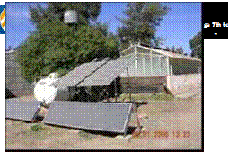
The system is made up of (Fig. 1):
• Two flat water collectors measuring 0.80 m x 2.96 m each.
• A hot water tank for house heating with a 110 l capacity, 5,75 W energy consumption, 235 l/h recuperation and a work capacity of 3,4 kg/cm2
• A 100 l water tank
• A 1/2 HP bomb for water circulation through the beds from the collectors to the hot water tank.
• Two 1” electrovalves and a 24 V-AC tension
• Two retention valves.
• “Thermostat” type sensor with a 30 — 90 °C range.
• A flow meter.
Sensors location
Three sensors were located inside the chamber at 2.00 m, 6.00 m y 8.00 m of the front NET wall along the central horizontal axis, at 1.50 m above the central bed. Sensors were put at the water inflow and outflow of each collector, and a thermostat type sensor was inside them. In the hot water tank, sensors were placed at the water inflow and outflow, and one inside so as to have the ignition reference. To measure the water volume entering the bed, a flow meter was installed. Radiation was measured inside and outside the chamber. In Fig. 2, the distribution circuit of the sensors and the water through the collectors, hot water tank and benches are shown.
To monitor the variables of the inner and outer environment, a computer equipped with Keithely 1600 and Pclab 812 acquisition cards was used. Sensors were used to measure air temperature type LM (semiconductor); Vaisala capacitive tips for humidity, Kipp & Zonen radiometers and LICOR 200SA pyranometers for solar inner and outer radiation, and a LICOR analogic lux-meter for the ilumination level.
 |
 |
Fig. 1. View of the propagation chamber and the sun — Fig.2. Diagram of the water distribution circuit gas system
Vegetal Material:
Walnut: young plants — six monts old — of native walnut were selected. They were obtained from seeds cultivated in greenhouses, and cv. Sunland walnut grafts 0.025 a 0.030 m long collected and kept in a cold chamber at 5°C.
Carob: stems from plants of the Central Valley of Catamarca were used for this work. They were 2 to 3 and 8 to 10 years old. Stems were taken from the basal part of the branch and were from 0.25 to 0.30 m in length and from 0.0025 to 0.0030 m in diameter. On each stem, 4 to 5 buds and leaves cut in halves were left to avoid greater perspiration. At the base of the stem, a bark scraping was made to favour the contact of the surface with the hormone solution.