Как выбрать гостиницу для кошек
14 декабря, 2021
Сегодня каждый, кто собирается в отпуск и не знает, с кем оставить своего котика или кошку, может во[...]
Four simulation studies were performed in Subtask C. Three of them were using more or less the reference conditions defined in Subtask A [3]. One of them dealt with a complete different application to reduce boiler cycling by introducing a PCM store.
The simulation results from HEIG-VD in Yverdon-les-Bains, Switzerland concerning the advantage of macroencapsulated PCM in solar combisystems are shown in Fig. 2 [4]. It should be
|
Fsav, therm(w) [-] Fig. 2. Difference between pure water and water + PCM system. (PCM gain = Fsavtherm(W+PCM)/Fsavtherm(W) — 1) |
![Подпись: Fsav,therm(w) [-] Fig. 2. Difference between pure water and water + PCM system. (PCM gain = Fsavtherm(W+PCM)/Fsavtherm(W) - 1)](/img/1128/image411.gif) |
reminded that the proposed system has been analysed only from the simulation side, where a water tank storage filled only with water or filled with water + PCM (paraffin RT35) is compared.
To evaluate the impact of the PCM on the performances, it is possible to define the energy gain between the Fsav, therm for the tank with PCM (Fsav, therm(W+PCM)) and only with water (Fsav, therm(W)). If this gain is higher than 0, then the PCM brings an advantage. As it can be seen in Figure 3, the gain due to using PCM is low. A decrease of the RATIO according to the increase of the Fsav, therm can also be noticed. But it should be remembered, that when the Fsav, therm is high, the solar installation is oversized. As it can be seen, adding a PCM becomes less interesting when the solar system is oversized. This is due to the fact, that when oversized, the storage of heating is less relevant.
The fractional thermal energy savings fsav, therm are a measure of the percentage of the auxiliary (non-solar) energy input for heating that can be reduced by the solar system. This term does not account for electricity use unless it is used directly for heating. The efficiency of electricity production and distribution pel is 0.4 in all cases. Hereby Qboiler and Qelheater are the energy inputs of the solar combisystem with respective efficiencies pboiler and pel. Qboiler, ref defines the energy input of a boiler of a defined conventional heating system with an efficiency of nboiler, ref [3].
Qboiler __ Qel, heater
fm>er. = 1 — —( (Equation 1)
boiler, ref
According to the additional cost of adding the PCM and the environmental impacts results described in [2], this system with PCM does not show a substantial benefit compare to a storage tank filled only with water.
Only the long term heat storage with subcooled liquid PCM (BYG DTU, Department of Civil Engineering, Denmark, Fig. 3 [5]) shows the possibility to achieve 100 % solar fraction with PCM store volumes of about 10 m3 for a 135 m2 floor area passive houses (15 kWh/m2a space heating energy demand). Water stores have to be far bigger to achieve the 100 % solar fraction. 80 — 90 %
|
Fig. 3. Simulation model of BYG DTU, Department of Civil Engineering, Denmark [5] |
![Подпись: Fig. 3. Simulation model of BYG DTU, Department of Civil Engineering, Denmark [5]](/img/1128/image413.gif) |
solar fraction can be achieved also with water stores of 5 — 10 m3. Taking into account the long term heat losses of water stores the size reduction is far bigger.
At the Institute of Thermal Engineering (IWT), Graz University of Technology, Austria different hydraulic systems were investigated in terms of their ability to reduce boiler cycling operation [6]. In the following a description of the hydraulic systems, which are used in the simulations, is given. Table 2 shows a summary of all simulated concepts.
|
Table 2: Summary of all simulated system concepts [6]
|
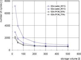
The results for the system with water storage (G2a) and for systems with water storage with integrated PCM modules (G2b) are shown in Fig. 4 for different storage volumes. In comparison to the systems without buffer storage the number of start-stop cycles is reduced strongly. Even with the smallest volume of only 25 litres of water a reduction of about 70 % (set temp. 50°C) or 90 % (set temp. 65°C) can be achieved. With increasing storage volumes the number of cycles decreases, whereby the potential for a further reduction is low for volumes above 200 litres. Because of the lower utilized temperature difference the number of cycles is higher with a boiler temperature of 50°C in comparison to 65°C. On the other hand the higher temperatures decrease the annual efficiencies of the condensing boiler by 2-3 %.
 |
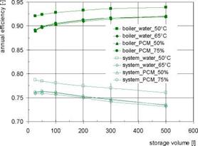 |
The integration of PCM modules (boiler set temp. 65°C in all cases) allows an enhancement of the storage capacity, resulting in a further decrease of the number of start-stop cycles especially with small storage volumes. There are only minor differences between the PCM volume fractions of 50 and 75 %. The integration of PCM modules hardly influences the annual efficiencies of the boiler and the system (Fig. 4, right).
Fig, 4. Gas boiler: annual number of start-stop cycles (left) and annual efficiencies (right) for different
storage volumes for systems with water storage (G2a) and for systems with water storage with integrated
|
2 6000 0) £ 5000 0 4000 -Q 0 3000 2000 1000 0 |
|
И n cycles eff_boiler eff system |
|
1.2 1.0 0.8 + 0.6 0.4 0.2 0.0 |
|
c <D О it= <D "to 3 C c ro |
|
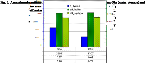
Fig. 5. Annual number of start-stop cycles and annual efficiency for the systems G3a (water storage) and G3b (bulk PCM storage) |
 |
PCM modules (G2b)
Figure 5 shows the number of start-stop cycles and the annual efficiencies for the system G3a (water storage) and the system G3b (bulk PCM storage). Due to the higher storage capacity of the PCM storage (assuming the same volume of 45 litres) in system G3b the number of cycles can be reduced by 50 % compared to system G3a. The annual efficiency of the boiler is also slightly higher, which is a result of the lower amount of heat produced in start-stop operation due to the higher storage capacity.
Phase change materials as heat storage theoretically offer an advantage compared to water stores, when the cycling temperature is close around the phase change temperature and the phase change can be used quite often. The other possible application is the use of the subcooling effect for seasonal storage. However, the investigations reported here showed only little advantages for macro-encapsulated PCM modules in combistores, PCM-stores with immersed heat exchangers and for PCM slurries for heat stores in solar combisystems and residential heating systems. The seasonal storage with subcooled PCM could be in principle a good solution. However the technical expenditure for this system is large.
[1] A. Abhat, (1983), Low temperature latent heat thermal energy storage: heat storage materials, Solar Energy 30 (1983) 313-332.
[2] W. Streicher, (ed). (2008), Laboratory Prototypes of PCM Storage Units, Report C4, of IEA Solar Heating and Cooling programme — Task 32, “Advanced storage concepts for solar and low energy buildings”, IEA-SHC (http://www. iea-shc. org/task32/publications/index. html)
[3] H. Heimrath, M. Haller, (2008), The Reference Heating System, the Template Solar System, Report A2, of IEA Solar Heating and Cooling programme — Task 32, “Advanced storage concepts for solar and low energy buildings”, IEA-SHC (http://www. iea-shc. org/task32/publications/index. html)
[4] S. Citherlet, J. Bony, (2008), System Simulation Report, System : HEIG-VD-W and HEIG-VD-PCM, Report C6.1, of IEA Solar Heating and Cooling programme — Task 32, “Advanced storage concepts for solar and low energy buildings”, IEA-SHC (http://www. iea-shc. org/task32/publications/index. html)
[5] J. M. Schultz, (2008), System Simulation Report, PCM with supercooling, Report C6.2, of IEA Solar Heating and Cooling programme — Task 32, “Advanced storage concepts for solar and low energy buildings”, IEA-SHC (http://www. iea-shc. org/task32/publications/index. html)
[6] A. Heinz, (2008), System Simulation Report, System: PCM storage to reduce cycling rates for boilers, Report C6.3, of IEA Solar Heating and Cooling programme — Task 32, “Advanced storage concepts for solar and low energy buildings”, IEA-SHC (http://www. iea-shc. org/task32/publications/index. html