Как выбрать гостиницу для кошек
14 декабря, 2021
Mathematical model of solar flat-plate liquid collector has been transformed into design tool KOLEKTOR 2.2. The design tool is a computer program with user-friendly interface created in
Visual Basic Studio environment. Detailed geometrical and physical parameters of individual solar collector parts are entered through appropriate tool cards (general design parameters, absorber, glazing / insulation, calculation, see Fig. 3). Besides the principle parameters and characteristics the tool allows to enter also internal air pressure in the collector (for modelling both flat-plate atmospheric and evacuated collectors), slope of collector, type of heat transfer fluid (water, water — ethyleneglycol solution, water-propyleneglycol solution with defined mixing ratio) and to choose the separate free-standing installation or building envelope integration of collector (with given thermal resistance of envelope). Design tool allows to choose from various empirical models for calculating the heat transfer coefficients (e. g. forced convection in pipes, natural convection in air gap, sky radiation, wind convection) collected from different authors and thus to trace the influence of heat transfer coefficient model selection on the calculated performance of solar collector. There is often a number of possible models for calculation of heat transfer coefficients available but with rather different resulting values, e. g. wind convection models, and their influence on calculated collector performance should be verified (sensitivity analysis). Data entered into tool cards and choices made can be saved into text file (*.kol) for later use.
|
Fig. 3. Tool cards of KOLEKTOR 2.2. |
Output results of the design tool are the solar collector performance for given boundary conditions or efficiency curve of solar collector at standard boundary conditions (ta = 20 °C, G = 800 W/m2, w = 3 m/s) related to mean fluid temperature. Heat transfer coefficients in the individual parts of solar collector and nominal stagnation temperature tstg are displayed for detailed analysis. Results of calculation (collector efficiency curve) can be saved into spread-sheet file (*.res).
Emission and distribution are the same for three cases. For distribution, it consists in cold water and hot water pipe network. Pipe losses are taken into account as well as pumps consumption (80% of pipe losses are recovered by building). Pump for hot network is only operating when there is a heating demand while cold network pump is always operating. Fan Coil Units (FCU) are installed for cooling and heating emission, fans are only in use in case of cooling or heating demand. The number of fan coil units is based on maximum cooling or heating load. There are 25 FCU for each floor (7 in meeting room and office South, 11 in office North).
Fig.3. shows the simulation results of the temperatures of the solar collector, the heat storage tank, the boiler and the DHW use. Fig.4. shows the simulation results of the solar radiation on the collector, the collected solar energy and the DHW heating load. Figs.3 and 4 show the results for the collector tilt angle of 40 degrees and the azimuth of 0 degrees (due south) in Tokyo.
The large differences were not found for the outlet temperatures of the solar collector. The temperatures of the heat storage tank were almost the same. The bottom temperatures of the tank in Cases 2 and 3 were close. The difference in Cases 1 and 3 was about 6 degrees C while the difference in Case 2 and 3 are very small. The temperatures of the DHW supply in Case 1 are lower than Cases 2 and 3, since the flow rate in Case 1 is very small.
The differences in collected solar energy in Case 1 to 3 were small in Fig.4.
Table 2. shows the comparison of the yearly performance. The solar radiations on collector are almost the same. For the collected solar energy, Case 3 with the short time increment is the largest, but almost same as Case 2. The collector efficiencies for Cases 1 to 3 are 36.8 %, 38.6 % and 38.9 %, respectively. For the DHW heat load, Case 1 is the largest. The solar contributions for Cases 1 to 3 are 55.8 %, 60.7 % and 62.5 %, respectively. The results of Cases 2 and 3 are close. Therefore, it was considered that the suitable time increment is 10minutes. Case 1 is different from Cases 2 and 3. However, the simulation with 1 hour increment can be considered that the results may not over estimating the system performance.
Simulation of total system performance in five cities
The detailed system simulation was carried out for 42 combinations of collector tilt angle and azimuth as shown in Table3. for five cities in Japan, Sapporo (43 degrees N), Morioka (39 degrees N), Sendai (38 degrees N), Tokyo (35 degrees N) and Kagoshima (31 degrees N). Five cities were selected to examine the
|
|||||||||||||||||||||||||||||||||||||||||||||||||||||||||||
|
|||||||||||||||||||||||||||||||||||||||||||||||||||||||||||
|
|||||||||||||||||||||||||||||||||||||||||||||||||||||||||||
|

 |
/
 average primary energy was less than the case of without solar DHW heating system by 10
GJ. The CO2 emission was around 52 % of the average of the solar DHW system.
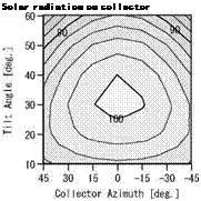
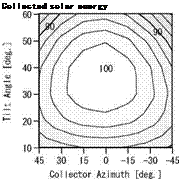
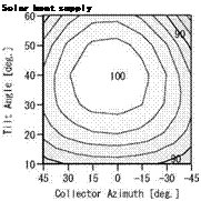
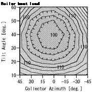
Fig.6. shows the comparison of the yearly performance of with the combinations. As the contour, the combination of the collector tilt angle of 40 degree and the azimuth of 0 degree is expressed as 100 %. The results of 100 % are the combination of the collector tilt angle from 30 to 40 degrees and azimuth within 15 degrees. When the collector tilt angle is too low and too high or azimuth is largely deviated from 0 degrees, collector performance is reduced. However, the difference is within 10%.
Table 5. shows the average yearly performance in five cities in Japan. The collector efficiencies are close in each region. In Sapporo, the average temperature of city water was the coldest. Therefore, the DHW heat load is highest in five cities. The solar contributions for DHW heating load in Sapporo, Morioka, Sendai, Tokyo and Kagoshima were 44.3 %, 45.7 %, 51.0 %, 57.0 % and 65.5 %, respectively.
|
Table 5. Comparison of average yearly performance in five cities
|
The boiler heat loads with the solar DHW system in five cities are 9.3 GJ/year, 8.8 GJ/year,7.5GJ/year, 5.8 GJ/year and 4.1 GJ/year, respectively.
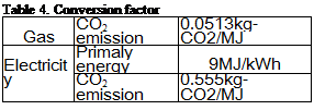
The electricity consumption of the collector pump and the boiler were 87 kWh/year and 111kWh/year (278 MJ/year), respectively. The CO2 emissions were reduced to 63.1 %, 62.2 %, 57.5 %, 53.5 % and 47.8 %, respectively.
1) In order to find the suitable time increment in the simulation of the solar DHW system, the results of three time increment cases, 1 hour, 10 minutes and 1 minute were compared. The simulated results of 10 minutes and 1minute time increments were very close.
Therefore, 10 minutes time increment is considered to be the suitable for the solar DHW heating system simulation. However, in case of 1 hour time increment, the simulated result in solar energy contribution was lower than other two cases by 8 % and the auxiliary boiler load was larger by 14 %. This means that the simulation results with 1 hour time increment does not overestimate the system performance.
2) The comparison of the total system performance of the solar DHW heating system for the combination of collector tilt angle and azimuth in Tokyo was carried out. The difference of the system performance was within 15 % when the collector tilt angle is from 10 to 60 degrees and azimuth is within 45 degrees from due south. As the similar results were found for the effect of collector tilt angle and azimuth on the total system performance in other four cities, there are many possible ways of the tilt angle and azimuth of collector in designing the solar DHW system in Japan.
3) The average solar system performance was compared in five cities in Japan. The simulation result showed that the solar contribution for DHW heating load in Sapporo, Morioka, Sendai, Tokyo and Kagoshima were 44.3 %, 45.7 %, 51.0 %, 57.0 % and 65.5 %, respectively. The difference is caused by the in DHW heating load which strongly influenced by the city water temperature.
[1] T. Kusunoki and M. Udagawa, Effect of Hot Water Heating Load in Solar DHW Heating System, Proceedings of JSES/JWEA Joint Conference 2007, pp.217-220. (In Japanese)
[2] T. Aoki and M. Udagawa, Effect of Building Orientation for Overall System Performance of Solar House — Application of EESLISM for solar house design-, Proceedings of ISES RENEWABLE ENERGY 2006.
[3] T. Aoki, M. Udagawa and H. Roh, Optimum Collector Arrangement for Solar Space and Hot Water Heating System, Proceedings of ISES EuroSun2006.
[4] M. Satoh and M. Udagawa, Study on the Simulation Time Increments for Solar DHW Heating Systems, Proceedings of JSES/JWEA Joint Conference 1997, pp. 129-132. (In Japanese)
[5] M. Udagawa, and M. Satoh, Energy Simulation of Residential Houses using EESLISM, Proceedings of Building Simulation ‘99, pp.91-98. (In Japanese)
[6] SHASEJ Report, Estimation of CO2 emission from residential house for validation the reduction effects of heating, cooling and hot water systems, SHASEJ, 2008.3
[7] Architectural Institute of Japan, Expended AMeDAS Weather Data, 2005. (In Japanese)
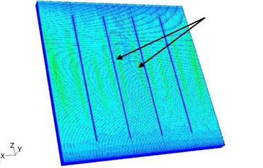
The display of the velocity profile was completed in Figure 3. Velocity was observed to increase with the longitudinal length and then decrease as it gets closer to the top of the collector. This can be explained by the accumulation of hot water at the top of the collector reducing the velocity boundary layer and promoting diffusion of heat with time. A horizontal plane would show that high velocities occur at the absorber plate where high temperatures take place. It is observed in Figure 3 that an increase, followed by a decrease, pursued by an increase in velocity occurs between the fins. This decline in velocity in the middle of the fins suggests the addition of fins to increase the velocity magnitude. The horizontal view of velocity profile supports this observation.
![]()
![]()
![]()
![]()
![]()
 7.43Є-03 7.06e-03 6.69e-03 6.32Є-03 5.95e-03 5.57e-03 5.20e-03 4.83e-03 4.46e-03 4.09e-03 3.72e-03 3.34e-03 2.97Є-03 2.60e-03 2.23e-03 1 86e-03 1.49e-03 1.11e-03 7.43e-04 3.72Є-04 O. OOe+OO
Results showed that the overall velocity increased with time until it reached a peak value from which velocity magnitude declines with the passage of time. The increase is due to a high heat flux through the fins to the water occurring after the initial capacitance effect of the system. With time, hot water builds up at the top of the collector resulting in a decline of heat transfer and therefore heat is diffused from the system.
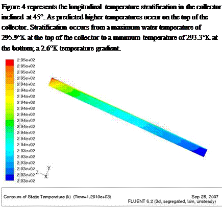
Figure 4: Longitudinal water temperature stratification — 4 fins, side view, after 20mn
In an attempt to improve the heat transfer one fin was added to the original ICS-SWH design. New 3D velocity and stratification analysis were undertaken for the five fin ICS-SWH.
Szent Istvan University, Department of Physics and Process Control, Pater K. u. 1., Godollo, H-2103 Hungary
Corresponding Author, Kicsiny. Richard@gek. szie. hu
This paper introduces the realization and application of a block-oriented type physically-based model of solar heated thermal systems which is able to work with inputs from either measurements or meteorological models. On the basis of measured data of a particular combined, with more consumers, solar heating system the validation of the model is shown in domestic hot water heating operation. Using meteorological models for the same system in swimming pool operation it is also shown that there are significant fluctuations in the pool temperature as the evaporation heat loss coefficient changes within the bounds of different recommendations in literature.
Keywords: combined solar heating system, physically-based modelling, measurements, meteorological models
In view of the possibility of harnessing solar energy in swimming pool applications and the increasing amount of such installations, it is important to develop the efficiency of solar heated systems. In order to improve any simple or combined solar heating system, physically-based modelling is an exact, theoretically overseen tool. Former works on modelling of solar thermal systems can be fond in [4], [5] and [6].
The aim of this work is to realize a mathematical model corresponding to solar heating systems that takes into account all the substantial energy components as well as the physically-based specifications of them. Physical bases are well described in details in [2]. In addition one should be able to validate it using measured data. The model should be able to work up inputs from either measurements or meteorological models and should be flexible for easy adapting to any similar systems. A method of meteorological modelling can be found in [1].
The use of GIS in renewable energy that began in the 90s decade went through considerable progress and as a result various decision support tools were developed [1]. The GIS applications that were developed can be classified in three groups: GIS as a decision support tool for integration of renewable energies on a large scale and at a regional level, GIS for assessment of distributed energy generation and that connected to the electric network and GIS for decentralized production systems and autonomous production of electricity.
The GIS decision support tool for integration of renewable energies on a large scale and at a regional level (European Community) propose to analyze: evaluation of renewable energy potential (solar, aeolic, biomass and minihydraulic), its participation in relation to primary regional energy and the potential reduction of CO2 emissions [2]; evaluation of economic and potential renewable energies to identify regions of the European Community where the renewable sources were competitive at a determined risk [3]; evaluation of renewable energy potential, calculate the final use in the region and according to the scenario the insertion of a given renewable energy, makes its dimensioning and evaluates the economic impacts [4].
The GIS for evaluation of distributed generation, connected to the electric network considers the following renewable energy sources: aeolic, biomass and solar. The majority of GIS applications for aeolic energy deal with the optimum localization of the aeolic plants, consider the potential of the resource, the infrastructure for access and transmission lines and environmental restrictions and land use [5, 6, 7] , also Matthies [8]considers petroleum platforms, shipping routes and submarine lines for study of optimum localization of offshore aeolic farms. Marnay [9] developed a study of the use of photovoltaic solar energy installed on roofs of residences in the USA using GIS. The project included a municipality level resolution and considered the following variables: solar irradiation, average price of electricity and spatial distribution of the population.
A peculiar characteristic of biomass utilization is the necessity of transport from the local of cutting to a central transformer which makes the geographic proximity of the offer a determining factor for the final cost of the generated electric energy. Noon [10] developed a GIS for the Tennesy Valley, USA which considered the following variables: the characteristics of places of biomass offer, places of demand and transport costs, technical characteristics of the plants, forestry residues or cultivated forests, road networks and administrative limits. Voivontas [11] developed a work on the Island of Crete about the biomass potential for generation of electric energy. It deals with the combination of evaluation of the resources (theoric and/or available), the transport cost, the identification of optimum locals for biomass cultivation and the definition of the size of the plant for determining its economic competitiveness in the presence of conventional sources. Similarly in Spain one was developed IBERINCO [12].
SOLARGIS [13] is a GIS for rural electrification with renewable sources of energy. It is a paradigm of a GIS tool for this purpose as much for its completeness, relatively ample diffusion of its use as also for the periodic up-dating and improvements. The principal objectives of its development were: the demonstration of value of the GIS methodology for the development of the implantation of renewable sources for rural electrification, demonstration of its applicability in some target regions and proper construction of a GIS tool for analysis of the potential renewable sources [13]. The SOLARGIS methodology intends to obtain the best option for rural electrification, in isolated locals using renewable systems or not, being individual user or users connected to a local mini-network. The isolated residence could be electrified by PV systems, aeolic, gas generator, diesel group or interconnected to a network. A mini-network could be supplied by group diesel or hybrid aeolic-diesel system. The high potential regions are determined through comparison of equivalent costs of electrification of the energy systems considered. For this calculation, with a resolution of 1 km2, the following information is used: habitation density, mean annual global irradiation on the collector plane, mean annual wind velocity and distance of residence to electric energy network. SOLARGIS was applied in Tunis (Tunisia), Kairouan (Tunisia), Marrocos, Sicilia (Italia), Andaluzia (Spain), Murcia (Spain), Crete (Greece), Island of Santiago( Cape Green), Para (Brazil) and Karnataka (India).
NREL [14] is a GIS tool that is accessible via web that permits visualization of monthly mean solar irradiation with a spatial resolution of 40 km x 40 km (low) and in high resolution 10 km x 10 km for a collector plane facing the south, with the tilt in relation to the horizontal equal to latitude or the direct normal solar irradiation. In the same way it produces estimates of aeolic energy on an annual base, for low resolution (1/3 or 1/4 degrees) and high resolution cell size of 20-1000 m. Also the tool includes an estimation of the biomass potential derived from the different sources (agricultural residues, waste, forestry residues, among others).
RENEWABLE ENERGY ATLAS OF THE WEST [15] is a GIS tool that is accessible via web which synthesizes the data and maps on renewable energies for eleven American states that are situated in the West of America: Arizona, California, Colorado, Idaho, Montana, Nevada, New Mexico, Oregon, Utah, Washington and Wyoming. At a regional level (West American) the atlas shows, solar, aeolic, biomass and geothermic resources, the present mix of electricity supply, the renewable energy systems installed and information on public policies for stimulating the use of renewable energies. Also the present capacity of transmission lines, an estimation of charge growth in the region, aspects of soil use and environmental impacts are presented. In other sections the Atlas makes an in detail account of this information at state level.
PV-GIS [16] is a GIS application that is available in real time in web for calculating the photovoltaic solar energy potential in Europe. The user can navigate over solar irradiation maps and obtain the solar irradiance incident on a photovoltaic module positioned at different inclinations. A second application permits the obtention of the monthly mean daily profile for a given month and different positions and inclinations of the module. Finally a third application calculates the photovoltaic electric energy for a given configuration of PV systems that are localized in a given place.
Even if many works [3] had analyzed the problem of the heat losses due to radiation and conduction, it is important to introduce a short summary. The first term to be evaluated is the net
inward radiative heat flux defined as:
![]() (4)
(4)
The irradiation, G, in general case can be written as:
■ ■ ■: ■ (5)
J is the radiation heat loss from the total irradiation arriving on the solar tube, is the mutual irradiation, FoniiJ is the ambient view factor, a is the Stephan-Boltzmann constant.
Solving for the surface-to-ambient radiation, qr:

Assuming Gm= 0 and Famb= 1, the solution has given for a single tube. A computation of./takes count of the incident angle on the surface of the solar tube, of the reflectivity/transmittance of the first borosilicate glass shell, of the optical properties of the cermet layer. In the surface of a single evacuated tube together with the parabolic concentrator, G has a value of about 160W. Table 1 represents the radiation heat losses due to different causes. The radiation is converted into heat energy from the cermet layer and transferred by conduction phenomena to the borosilicate glass and to the different layers (aluminium, air and copper) until the vector fluid.
The Fourier amplitude sensitivity test (FAST) is a quantitative method [3]. It computes the contribution of each parameter to variations of the target function. It is called the “main effect” and defined as
S, = varx.|£ (y|x >’ (2)
j var(y)
Variations in numerator and denominator of (2) are multidimensional integrals over appropriate spaces. Their computation is very expensive. In the FAST, they are replaced by the one-dimensional integrals over the some curve exploring the space
x (s) = K (sin o,-s) (3)
In the next stage of the method, the target function y(s) = y(x(s),x2(s),…,xn(s)) is expanded in the
+да
Fourier series y(s) = ^ {A. cos js + Bj sin js}, and then the spectrum Л2 = Aj + B^ of the Fourier
J=-n
series expansion is used for calculation of the main effects.
The FAST algorithm can quantify influence of the parameters but for this it requires more calculations of the target function than the Morris method. If the system depends on very large number of parameters then it would be reasonable first to apply the Morris method and then to quantify the influence of only the most important parameters by the FAST algorithm.
L. Bujedo1*, J. Rodriguez2, P. J. Martfcnez3, and J. Vicente1
1 CARTIF, Parque Tecnologico de Boecillo Parc 205, 47151 Boecillo, Spain
2 Institute for Renewable Energy, EURAC Research. Viale Druso 1, 39100 Bozen/Bolzano. Italy
3 University Miguel Hernandez, Av. De la Universidad s/n, 03202 Elche Spain
* Corresponding Author, luibuj@cartif. es
Abstract
The present work, describes the main features of a software developed by the research centre CARTIF under the programming environment LabVIEW ®, which allows to visualize all of the variables collected by means of the installation’s instrumentation to measure different values (temperatures, flows and pressures), and the meteorological station (direct and diffuse radiation, ambient temperature, relative humidity, etc.), and its subsequent exploitation.
The program apart from calculating the identification parameters for the different elements: performance curves for the collectors, efficiency of the heat exchanger, looses on tanks or hydraulic performance, allows the analysis of the system along a time period in a particular date doing a balance of the energetic variables during this period. With the previously recorded values is calculated the average performance for the different elements.
This program has been very useful for other works based on simulation using TRNSYS, as it shows directly the values to be introduced on the model in order to compare the real system and the simulated one.
Keywords: solar cooling, identification, performance, LabVIEW ®.
As [1] establish one of the problems that solar cooling installations have to face is “the lack of practical experience and acquaintance among architects, builders and planners with the design, control and operation of these systems”.
Despite there are an important number of operative installations, there is no information related to their exploitation. Among the causes can be found: insufficient monitoring of the different heat flows, what prevent to close the power balances. Some of the errors usually committed, can be for example the lack of flow measures because there are constant flow pumps, and with the system working the flow must be constant as well. Nevertheless the experience becomes evident that it is not like this, since the more elemental change on the hydraulic structure of the installation modify the value of this flow, such as for example to feed the generator with the boiler or to do it with the solar installation.
Another problem is to use measuring systems that does not allow to store the values into files, and so sometimes, it must be done a manual collection of the data measured.
On the contrary to have measures of temperatures, flows and pressures and record they periodically
(0.5 minutes), make possible the analysis of the installation performance or the identification of the
different elements and posterior modelling. Allows as well, detection of operation or design failures. The authors would like to highlight the importance that monitoring has for installations as a way to know what is happening and a tool obtain conclusions to learn from the things well done as well as for those wrong.
The problem of air circulation and heat transfer can be modeled through mass, momentum and energy conservation equations. Assuming incompressibility, the mathematical formulation for the general problem can be written as: Find u, p and в satisfying the following system, div (u) = 0, in Qx [0, T], (1)
Au
p — + p (Vu)u — 2p div s (u) + Vp + р^Р(в-в) = 0, in Q x [0,T], (2)
с)в
pcp — + pc^u. (V в) — к div Ve = 0, in Qx[0,T ] , (3)
Vu. n = 0 in Г„ x [0,T], u(x, t) = u(x, t) in Tux [0,T],u(x,0)=u0 in Q x [0,T], kVe. n = 0 in Гd x[0,T], в(х, t) = в in Г x[0,T] and в(х,0) = во(x), in Q
where: u = u(x, t) is the velocity vector, p=(x, t) is the pressure, в = в(х, t) is the temperature, p is the viscosity, p is the density, к is the thermal condutivity, в is the reference temperature, n is the normal vector, c is the
specific heat, p is the coefficient of thermal expansion, g is the gravity vector, e(u) = ^(Vu + Vur), Q is the bounded domain with boundary Г = Гц иГ, = Гс иrd with Гц пГ, = Гс пГd =0 and the time t є [0,T].
The term pgp(e — воо ) allows the coupling of the air circulation and the heat transfer problems.
2. Methods
For the air circulation problem the numerical solutions are here obtained by a stabilized mixed finite element method that allows us to deal with the difficulties that come from the first equation system, Equations (1) and (2): the difficulty in constructing approximation spaces for problems with internal constraint; non-linearities of the convective type and numerical instabilities when advection effects are dominant. Here, a Petrov-Galerkin type method [6] was implemented and applied to analyze indoor air circulation cases, ensuring stability for dominant advection and for the internal constraint. In the case
of a heat transfer problem a stabilized finite element method was implemented — Streamline Up-wind Petrov-Galerkin (SUPG) [7].
Being L and H1 the usual Hilbert spaces and Rf the Lagrange polynomial space of the degree l and class C0. Then, defining the following approximation spaces
V={u„ є (H0Q)nRf))2,u„(x, t) = Uh(x, t) in Г, }c (HW, V0={v„ є (H0Q)nR(Q))2,v„(x, t) = 0 in f }c (Hf))2, Ph=[pf є (L2(Q) n Rf (Q)); I PfdQ = 0jc (L2(Q)), Sh = {% % (x, t) є(н1 (Q)n Rf (Q)) ,% (x, t) = % (x, t) in Гс }c (H*(Q)), Sf = {s„ sh (x, t) є (H1 (Q)n Rf (Q)), Sf (x, t) = 0 in Гс j c (H *(Q)) with the usual norm ||u||2 = | |u 110+lVull0 of Hl and N HIp0of L2.
The wind field can be determined by solving the following formulation:
Find {uh, ph } є Vh x Ph satisfying the following system B (uf, Ph; vh, q) = ° v (vh, q) єКx Ph, where:
((Vvh ) ah — 2^ div Фи ) + V4h ))h+H ph, 4h ), v vh є Vh e Чи є Ph.
with у << 1 and and Д stabilized parameters suggested by Franca and Frey [6].
And find %(x, t) satisfying the following system:
With r= kuVs^,the SUPG stabilized parameters suggested by Brooks and Hughes [7]. The time discretization has been done by backward Euler finite differences.