Как выбрать гостиницу для кошек
14 декабря, 2021
Fig.1. shows the system diagram of the solar DHW heating system [5]. The solar collector is a flat plate type with selective absorption surface and one glass pane.
The total collector area is 6 m2 and the storage tank volume is 300 litters. The effectiveness of the built in heat exchanger in the tank is assumed to be 30 %. The input electric power of the motor of the collector circulation pump is 35 W. The auxiliary boiler efficiency is assumed to be 76.2 %.
The simulation tool EESLISM [6] was used. Usually, the time increment of one hour is used in the simulation. However, smaller time increment was examined in this study. Table1. shows the simulation cases examined in this study. The time increments used to examine are Case 1: 1 hour, Case 2: 10 minutes and Case 3: 1 minute.
The standard weather data prepared as the Expanded AMeDAS Weather Data [7] and the supplied city water temperature data prepared by the Solar System Development Association were used in this simulation.
|
Fig.3. Comparison of simulation results by three time increments for temperature for the collector tilts angle 40 degrees and azimuth 0 degrees in Tokyo |
The modelling process was carried out for 3D analysis using CFD-Fluent 6.2 software. Gambit 2.2 was used to mesh the model. The simple and regular geometry of the model suggested the use of a quad structured mesh of size 1mm. Two different boundary condition types were applied on the absorber plate for tests, depending on the purpose of the simulation. Optimisation simulations used constant heat flux of 300W/m2 as the boundary condition on the absorber plate. Constant absorber plate temperature boundary condition was taken when comparing the heat absorbed by the two ICS-SWH designs. According to those conditions the program calculated the temperature field in the geometry and as a result values at the nodes were displayed.
Stratification is essential for the good performance of a solar collector and is significant when trying to optimise the collector for draw off. However better mixing in the tank results in higher rates of heat transmission when trying to get solar energy into the water. Then the addition of fins might give a differential of temperature lower from the top to the bottom of the ICS-SHW but will optimise the transfer of energy into water. A CFD stratification analysis was developed for the four fin ICS-SWH design and then undertaken for a second design using five fins to compare both water stratification and velocity magnitude for a given time and heat transfer through time.
3.1. Extended heat transfer fins
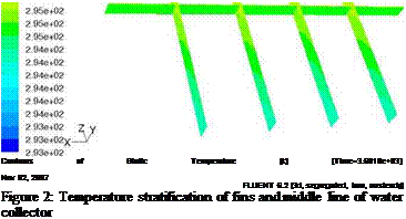
A good understanding of the influence of extended surfaces is important when seeking performance enhancement of the ICS-SWH. Figure 2 represents the temperature of the fins with height after a lapse time of 60 minutes and a simulated heat flux on the absorber plate of 300 W/m2. Heat is transferred through the fins from the top of the collector to the bottom where the water temperature is cooler. This results from gravity and buoyancy effects. Water with different temperatures will settle at a corresponding height in the ICS-SWH according to the density of the fluid. Hot water of low density will naturally settle in upper layers while cold water of high density will fall to the bottom layers. During the first three hours of the charging process, high temperature stratification occurs in the ICS-SWH. With time, temperature in the upper layers get fully established and reach an equilibrium influencing the lower layer to increase in temperature and therefore decrease the density gradient of water inside the ICS-SWH.
 |
In order to ease the comprehension of the analysis process a discussion of the original four fin collector design is discussed below.
The energy balance is considered for each component of the CPV receiver:
Tc, Tvb and the fluid, Tf and Tfo. Some geometrical characteristics of the CPV receiver and the silicone oil properties are given in Table 1.
3.1. Solar energy model
The irradiance absorbed by the vessel top, solar cells and vessel bottom are given by:
Ib = CR x I x a
vb g
As input for the model, the optical properties of the materials are used (Table 2).
Table 2. CPV receiver optical parameters
|
Parameter |
Absorptivity |
Emissivity |
Transmittance |
|
Glass |
0.05 |
0.90 |
0.90 |
|
Solar cells |
0.80 |
0.35 |
— |
|
Silicone oil |
0 |
— |
1 |
A basic and wide spread method is used to estimate the photovoltaic power output [18]:
E = CRX- Ere, [1 + T(T. — Trf)] (9)
1 ref
Where I is the incident irradiance, E is the power output, T is the temperature, subscript ‘ref refers to standard testing conditions, r is the power correction factor for temperature(I = 800^^2 ,
![]()
If = 1000W/ 2 , Ef = 246.8W/ 2 , Tf = 298K, y = -0.65%/K ).
The models above are analyzed to simulate solar cells temperature (Tc), vessel top temperature (Tvt), vessel bottom temperature (Tvb) and fluid average temperature (Tf).
Fig. 3shows the effect of concentration ratio on temperature when wind speed, ambient temperature, fluid inlet temperature and its volume flow rate are constant. The solar cells temperature is increased from 312K to 343K as concentration ratio is increased from 100X to 300X. So, if solar cells are operated in more than 300X, other parameters need be changed. Fig. 4 shows the four component temperature as a function of fluid volume flow rate at fixed wind speed, ambient temperature, fluid inlet temperature and concentration ratio. It is obvious that solar cells temperature and vessel bottom temperature varied with great ranges at beginning, then changed smoothly. A optimal fluid volume flow rate must be existed at a certain condition. Fig. 5 represents the variation of the four component temperature as a function of fluid inlet temperature at fixed wind speed, ambient temperature, fluid volume flow rate and concentration ratio. As an important parameter, the four component temperature is increased with its increased. The effect of environment variables including ambient temperature and wind speed on the four component temperature are shown in Fig. 6 and Fig. 7. The temperature of the four components has little change when ambient temperature and wind speed increased.
The main novelties of the HCPV system are the combination of a dish concentrator with solar cells immersed in dielectric liquid. The developed model predicts the effect of concentration ratio, fluid volume flow rate, fluid inlet temperature, ambient temperature and wind speed on solar cells temperature (Tc), vessel top temperature (Tvt), vessel bottom temperature (Tvb) and fluid average temperature (Tf). Results show that this kind of immersion operation of solar cells is an effective
method of cooling solar cells under concentrated light. Based on the experience achieved in the present work about high concentrated photovoltaic system with solar cells immersed in a dielectric liquid, the following topics need to be investigated: (1) construction of HCPV prototype, (2) the material stability, (3) determination the validation of the model and reliability of solar cells immersed in a dielectric liquid under concentrated light through experiments, (4) evaluation on feasibility and cost of the HCPV system.

|
|
|
|
|
|
|
|
|
|
|
|
|
|
|
|
|
|
|
|

|
[1] Antonio Luque, Gabriel Sala, Ignacio Luque-Heredia. Photovoltaic Concentration at the Onset of its Commercial Deployment. Progress in Photovoltaics: Research and Applications. 2006, 14:413-428
[2] Martin A. Green, Keith Emery, Yoshihiro Hishikawa, et al. Solar cells Efficiency Tables (Version 32). Progress in Photovoltaics: Research and Applications. 2008, 16:435-440
[3] G. Martinelli, M. Stefancich. Chp.7: Solar Cell Cooling, in: Concentrator Photovoltaics. Springer Berlin Heidelberg New York. 2007, 130: 133-149
[4] Pierre J. Verlinden, Allan Lewandowski, Carl Bingham, et al. Performance and Reliability of Multijunction lll-VModules for Concentrator Dish and Central Receiver Applications. 2006 IEEE: 592597
[5] Anja Royne, Christopher J. Dey, David R. Mills. Cooling of Photovoltaic Cells under Concentrated Illumination: a Critical Review. Solar Energy Materials & Solar Cells. 2005, 86: 451-483
[6] Welford, R. Winston. The Optics of Non-imaging Concentrators, Academic Press, New York, 1978
[7] A. Luque. Solar Cells and Optics for Photovoltaic Concentration, Adam Hilger, Bristol, 1989
[8] Blanco M, Alarcon D, Lopez T, et al. Computing the Solar Vector. Solar Energy. 2001,70(5):431-441
[9] Radziemska Ewa. Thermal Performance of Si and GaAs Based Solar Cells and Modules: a Review. Progress in Energy and Combustion Science. 2003, 29:407-424
[10] Jones A. D. Underwood C. P. A thermal Model for Photovoltaic Systems. Solar Energy.2001, 70(4):349- 359
[11] Davis M. W., Dougherty B. P., Fanney A. H. Prediction of Building Integrated Photovoltaic Cell Temperatures. Journal of Solar Energy Engineering. 2001, 123:200-210
[12] Garg H. P. Adhikari, R. S. Conventional Hybrid Photovoltaic/Thermal (PV/T) Air Heating Collectors
Steady State Simulation. Renewable Energy, 1997,11(3):363-385
[13] Garg H. P. Adhikari R. S. Transient Simulation of Conventional Hybrid Photovoltaic/Thermal (PV/T) air heating collectors. International journal of energy research, 1998,22:547-562
[14] Lee W. M. Infield D. G. Gottschalg R. Thermal Modelling of Building Integrated PV Systems. REMIC 2001.
[15] Duffie JA, Beckman WA. Solar Engineering of Thermal Processes. 2nd ed. New York: Wiley & Sons; 1991
[16] Biehl FA. Test Results and Analysis of a Convective Loop Solar Air Collector. Proc. 6th National Passive Solar Conf., Portland, Oregon, 1981: cited in [17]
[17] Altfeld K, Leiner W, Fiebig M. Second law Optimization of Flat-plate Solar Air Heaters. Part 1: The Concept of Net Exergy Flow and the Modeling of Solar Air Heaters. Solar Energy 1988;41(2):127±32
[18] Menicucci D, Fernandez JP. User’s manual for PVFORM: a Photovoltaic System Simulation Program for Stand-alone and Grid-interactive Applications; 1988. Sandia National Laboratories, SAND85-0376, Albuquerque, USA
The GIS (Geographic Information System) is a tool for computational treatment of geographical data and their associated data banks. It can be seen as a system of support for decision that unites spatially referenced data in an ambient of replies to problems. SIG groups, brings together and unites information. Through this available information becomes more accessible, and old information is put into a new context. In this project, the GIS is used as a tool that permits the integration and processing of information from diverse sources. From this it is possib
 |
the elaboration of strategies for implantation and management of rural electrification with renewable energy.
The GIS is a valuable tool for evaluation and development of the use of renewable energy resources in large regions, because it is a tool that is specially adequate for analyzing the spatial variabilities of the resource as well as also for resolving problems of management and planning of installation programs of decentralized systems, that are characterized by a great spatial dispersion.
The solar resource is strongly influenced by altitude, latitude and phytogeographical conditions; the aeolic resource for rugosity and topography of land and finally the biomass for its soil characteristic and pluviometric conditions.
In its turn, management and planning of renewable energy systems, is a task that besides knowledge on energy resource needs knowledge on the nearest technical assistance center, a diagnosis of the most frequent defects, information from installed systems, the proximity to electric transmission lines, the energy demand, the laws that regulate land use, the indices of human development and non electrification and tools for dimensioning the systems for the given local demand, among others. All these interelationships can be collected, quickly quantified and visualized spatially by the intrinsic management capacity of a GIS system.
When solar radiation come to an absorber layer, the spectral response of the ideal material should allow an absorbance on the bandwidth of incoming radiation and an emittance completely shifted in a different bandwidth. In this case all incoming radiation would be transferred into thermal radiation. Part of this radiation is lost under the form of emittance of the absorbing layer to the environment, part becomes thermal energy and is transferred to the below layers. The structure of the solar tube avoids conduction and convection losses to the environment due to the evacuated area between two concentric glass cylinders inside which area the absorbing material is deposited, usually on the external surface of the inner tube. The consequence is that, all conduction and convection losses concentrate in the various layers from the absorber to the vector fluid. The investigation of the problem starts with the evaluation of the efficiency for the analysed solar collector as certified according to EU certification EN.12975-2:2006. The solar collector efficiency is the ratio between the energy Q (energy density) absorbed from the vector fluid and the energy (solar energy density) incident on its external surface.
![]() (1)
(1)
and similarly, as usually reported, from the relation:
(2)
where tjq is the solar collector efficiency at TM = 0, ai and a2 are heat transfer coefficients, G is the total solar radiation and:
![]() (3)
(3)
where tm is the panel average temperature and is the ambient temperature. The relation (2) is
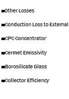
the main instrument to evaluate the quality of a solar collector, and is within the certification reports. The efficiency of the solar collector investigated in the actual work can be viewed in the Fig. 1. It starts at 71,8 % at ambient temperature and it’s referred to an incident radiation of 1000 W/m2. In the same graph are represented the various heat losses calculated from optical and geometric factors, tube materials, reflector characteristics and cermet thermal properties. "Other losses", the orange area, resume some other factors, the most relevant of whose is the thermal resistance between the cermet layer and the vector fluid.

![]()
 100%
100%
90%
80%
70%
60%
50%
40%
30%
20%
10%
0%
Fig. 1. Evaluation of the thermal losses on the real solar collector.
The Fig. 2 represents a section of the Evacuated Solar Tube (EST), selected for the modelling and used in the experimental prototype.
|
Temp |
Parabolic Concentrator (W)* |
Borosilicate Glass (W) |
Cermet (W) |
|
100 |
7.6 |
12.8 |
8.3 |
|
150 |
7.6 |
12.8 |
38.1 |
|
200 |
7.6 |
12.8 |
68.5 |
|
300 |
7.6 |
12.8 |
120.2 |
|
Table 1. Main contribution to radiation heat losses due to different optical behaviour and properties of the evacuated solar tube. * surface reflectance = 0.9 |
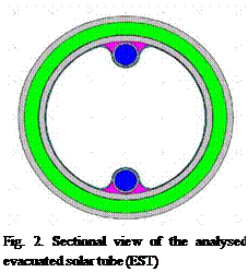 |
From external to internal the different layers of the EST are:
• borosilicate glass 3.3 tube — Glass TubeEXT ^EXT = 58mm; tb = 0.92, p = 0.062, a = є = 0.018 );
• vacuum (pINT~10-7 Torr, фЕХ1- = 56.4mm, фют = 47mm);
• cermet layer (a > 0.93);
• borosilicate glass tube — GlassTubeINT (фЕХЇ = 47mm, 5 = 1.5mm);
• computed air layer for materials tolerance between GTINT and aluminium profile (5 = 0.7mm);
• aluminium foil;
• copper tube (фЕХт = 7mm, фШт = 6mm);
• water (v = 0.556 m/s).
The problem of the evaluation of the heat loss and the development of a modified object with higher thermal efficiency is the first step to begin the research for a new device able to produce electrical, thermal and cooling power, with an efficiency higher than 70%. The first step is to build an evacuated solar tube with the capability to work at 250°C and more, without loosing thermal energy with consequences on its efficiency. The actual evacuated solar tube, at a vector fluid temperature of 523 K, has a thermal efficiency n = 0.23.
![image282 Подпись: [ y ( x,.. .Xj_ і, Xj + A, Xj+1,..., xk ) - y (x)] A](/img/1155/image282.gif) |
||
This method is qualitative and only ranks parameters by its importance which means influence on the target function [2]. However, it also allows to determine whether the parameters have linear or nonlinear effects on the target function or if they are involved in interactions with other parameters. The Morris method is based on the so-called elementary effects, defined for the ith parameter as follows:
The elementary effects dt(xm) are calculated at different parameter configurations xm, m = 1,…,M and then the distribution F of the elementary effects d; or the distribution G; of their absolute values is examined. The most informative sensitivity measures are the mean ц of the distribution G; and the standard deviation a of the distribution F. The mean ц is used to detect overall influence of the ith parameter on the target function y. The deviation a is used to detect the parameters involved in interaction with other parameters or those, whose influence on y is non-linear.
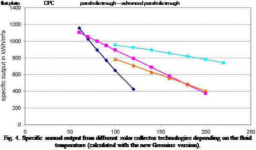
Greenius has been used to perform a study on the specific output of different solar process heat generating systems. The site chosen for this comparison is Almeria (Spain), with an annual sum of direct normal irradiance of 1918 kWh/m2a and a global horizontal irradiance of 1812 kWh/m2a. The main parameters of all solar fields investigated are shown in table 1. The aperture area is almost the same with small deviations caused by the area of a single collector unit. Solar only operation was assumed which might be interpreted as an additional solar plant operated as fuel saver in parallel to a large fossil process heat generating system.
The first 3 collectors are representing the state-of-the-art for their technologies and the last one (nominated as “advanced parabolic trough”) is a kind of hypothetical collector with the same optical performance as the existing 1ST type but with a vacuum tube receiver. Actually the heat loss characteristics from the Schott PTR70 Receiver have been used, a receiver which is installed in several of the parabolic trough power plants currently built in Spain and USA.
Figure 4 shows the results of the study: At low temperatures of 50 or 60°C the flat plate collector shows the best performance but if temperatures of 100°C or higher are needed, the CPC or the parabolic trough collector show better annual specific outputs due to their improved optics and the reduced heat losses. The difference between the CPC and the 1ST collector at temperatures above 140°C is insignificant. The CPC collector is able to compensate the performance gain of the tracking parabolic trough collector by the inclined installation and the vacuum tube. The curve of
the “advanced parabolic trough” shows the impact of such a vacuum receiver on the performance and as well the potential of parabolic troughs for process heat applications.
|
Collector type |
Flat plate |
CPC1} |
Parabolic trough |
Advanced parabolic trough |
|
Model |
Wagner C20 AR |
Paradigma CPC40 Allstar |
1ST |
IST with vacuum receiver |
|
Number of collectors |
110 |
66 |
20 |
20 |
|
Aperture area |
262.9m2 |
265.3 |
264m2 |
264m2 |
|
Peak optical efficiency |
85.4% |
64% |
71.5% |
71.5% |
|
Orientation |
South, 40° |
South, 40° |
South-Nord, 0° |
South-Nord, 0° |
|
Table 1. Important parameters of the solar collector fields |
|
1) CPC: Compound parabolic collector with vacuum tube |
 |
collector temperature in °C
Greenius offers further options to analyze different solar field layouts. Figure 5 shows the daily solar field output of the enhanced parabolic trough system for two different orientations of the collector axes. The left hand side of Figure 5 is based on south-north orientation of the tracking axis whereas the right hand side is based on east-west orientation. South-north orientation gives a maximized annual yield of 911 kWh/m2a, but a strong seasonal variation, and east-west orientation gives somewhat lower annual yield of 849 kWh/m2a with smaller differences between summer and
winter. These plots have been generated using the build-in capabilities of Greenius but the user interface specific frames are not shown to enhance the readability of the figure.
|
Fig. 5. Daily thermal output of the enhanced parabolic trough collector field for two different orientations of the collector axes: south-north (left) and east-west (right) |
Although Greenius offers also an economical evaluation of these projects by calculating a couple of economical and financial figures of merit, this feature has been omitted in this paper since the results are strongly dependent on the input data, particularly the specific system costs in €/m2. Due to the small number of parabolic trough plants for process heat applications, it is hardly possible to identify the costs for these systems. Therefore an economic comparison would have been based on rough assumptions, but the technical comparison shows, that parabolic trough are quite competitive to CPC collectors in the upper temperature range if they can reach the same cost level as the CPC collectors.
The software tool Greenius is now ready to study process heat generation by concentrating and non-concentrating solar collectors. It is therefore a valuable tool to perform fast case studies for different sites and different renewable energies.
The results of such a study for a site in southern Spain show that parabolic trough collectors may provide process heat with similar specific annual yield like CPC collectors at sufficient direct irradiance and at temperatures above 140°C. They offer the potential of much higher annual yields if the can be equipped with vacuum tube receivers, which CPC’s are already using.
Further tests and validation runs are scheduled, particularly for the parabolic trough models used.
A pilot plant is just under construction at Ennepetal, Germany, and first measurements from this plant will be available soon.
The work has been financed by the German Federal Ministry for the Environment, Nature Conservation and Nuclear Safety (Grant ID: 0329609A). The authors are responsible for the content.
[1] Quaschning, V., Ortmanns, W., Kistner, R., Geyer, M.: Greenius—A new Simulation Environment for Technical and Economical Analysis of Renewable Independent Power Projects. In: Proceedings of ASME International Solar Energy Conference Solar Forum 2001, Washington DC, 22-25 April, pp. 413-417.
[2] Quaschning, V.: Understanding Renewable Energy Systems. EarthScan London, 2005.
[3] Theunissen, P.-H.; Beckman, W. A.: Solar Transmittance Characteristics of Evacuated Tubular Collectors with Diffuse Back Reflectors. In: Solar Energy Vol. 35 (1985) Nr. 4, S. 311-320
[4] http://www. itw. uni-stuttgart. de/~www/ITWHomepage/TZS/Berichte. html
[5] Lippke, F.: Simulation of the part load behaviour of a 30MW SEGS Plant, Technical report SAND95- 1293, Sandia National Laboratories, Albuquerque, New Mexico, 1995
[6] Quaschning, V.; Kistner, R.; Ortmanns, W.: The Influence of Direct Normal Irradiance Variation on the Optimal Parabolic Trough Field Size: A Problem Solved with Technical and Economical Simulations. Proceedings of Solar 2002, Sunrise on the Reliable Energy Economy, ASME June 15-20, 2002, Reno, Nevada.
[7] Kruger, D., Hennecke, K., Richartz, J., Mumm, P.: Untersuchung von Leistungsfahigkeit und Einsatzmoglichkeiten eines Leichtbauparabolrinnenkollektors im mitteleuropaischen Klima, 12. Internationales Sonnenforum, 2000, Freiburg, Germany
 |
 |
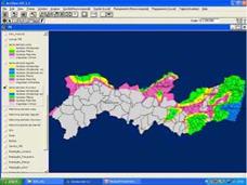
In the planning process for inclusion of renewable energy systems, after the definition coming from a multiple criteria approach ( energy resources, socio-economic indicators, indices of nonelectrification, among others) of the localities to be benefited, a dimensioning of the energy systems is necessary. The SIGA SOL permits the realization of dimensioning or simplified calculus for the following systems:
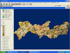
Figure 10 — SIGA-SOL functionalities, PV macro-planning, aptitude for the sugar cane and castor
 |
 |
bean plant for the state of Pernambuco
Figure 11 — SIGA-SOL functionalities, PV macro-planning, mean annual wind speed and prevailing
direction of the winds
 |
Autonomous photovoltaic system[2];
Photovoltaic system interconnected to the network;
Photovoltaic pumping system with given demand and depth of well [2];
Photovoltaic pumping system with given capacity and depth of well;
Annual electric energy generated by sugar cane bagasse and Annual electric energy generated by wind energy[3,4].
We thank the National Research Council (CNPq) , Brazilian Electric Centers SA (ELETROBRAS), The Sao Francisco Hydro Eletric Company (CHESF)and Coordination for Perfection of High Level Personnel (CAPES) for the aid in research projects on solar energy that provided material means and scientific ambient for carrying out this research.
[1] SIGA SOL 1.0 (2007) Sistema de informagao geografica aplicada a energia solar, Projeto ANEEL — CHESF, CT-I-192.1760.0.
[2] Tiba, C. , Fraidenraich, N. e Barbosa, E. M. S. (1998) Instalagao de sistemas fotovoltaicos para residencias rurais e bombeamento de agua, ISBN 85-7315-118-8, Ed. Universitaria da UFPE, Recife, Pernambuco.
[3] Amarante, O. C. , Brower, M., Zack, J. and Leite de Sa, A. (2001) Atlas do potencial eolico brasileiro, MME — ELETROBRAS-CEPEL.
[4] RETScreen (2007) Photovoltaic projects analysis, www. retscreen. net, Acess in April 2007.
P. R. C. Drach 1* and J. Karam F.2
1 PROURB-UFRJ, Faculdade de Arquitetura e Urbanismo da Universidade Federal do Rio de Janeiro, Brasil
2 Laboratorio Nacional de Computagao Cientifica, LNCC/MCT, Av. Gethlio Vargas 333, Petropolis, Brasil
* Corresponding Author, pdrach@lncc. br
Abstract
In this work we studied the temperature field behavior inside the third-floor of House VI in Vila 37. A “vila” in Brazil is a small private cul-de-sac with terraced houses. In this specific “vila” the original houses were very small and had no space between them, so they had to grow vertically. Nowadays the indoor air circulation presents a decreased state because the indoor ventilation is restricted to the facade windows and the urban volumes swallowed these houses.
In attempt to increase and promote better ventilation, we imposed some changes by introducing a wind-catch on the third-floor in this particular house. We also considered the incident solar radiation interference on the flat roof because this pavement receives the solar radiation directly. Computational simulations were carried out in both cases; with and without wind-catch. The analysis start by solving the air circulation problems, using a Petrov-Galerkin mixed stabilized finite element method applied to the full Navier-Stokes equations. The thermal problem is analyzed through a SUPG — Streamline Up-wind Petrov-Galerkin stabilized finite element method. The results obtained were compared and they suggest that this strategy shows good potential in achieving significant quality with reduced environmental and economical costs. Keywords: passive cooling, ventilation, wind-catch, solar radiation, finite element method
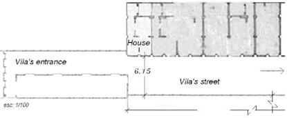
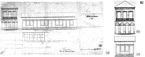
In this work we study the temperature field behavior on the third-floor of House VI in “Vila” 37. A “vila” in Brazil is a small private cul-de-sac with terraced houses, which share a common area and entrance gate. Vila 37 was built in the year of 1890 and is located in the neighborhood of Catete in Rio de Janeiro city, a tropical climate city, therefore hot. This “vila” initially was formed by a group of 24 one-floor houses and only one two-storey house located in its entrance. Figure 1(a) shows the photo of the entire original project. And some details such as the "facade of the street", Figure 1(b), in reference to the two-storey house located at its entrance and the facade of the standard one-floor house in Figure 1(c). Figures 2(a) and 2(b) present the plants of the house pattern and of the location of the group of houses where it is possible to observe how the houses were very small and that there was not space around them. These houses were constructed by a hard working population. They had originally just one room, one corridor, one bedroom and kitchen (Figure 2(a)). In agreement with old residents, the bathroom was located in the internal small street of the “vila” and it was collective in use and as a place for clothes washing. These documents were obtained in 2006 through the General Archive of Rio de Janeiro City — AGCRJ [1].

 |
 Two-storey house
![]() Houses
Houses
![]()
 |
|
(a)
Fig. 2. Original details (1890): house pattern plan (a) and house group location (b).
New buildings were constructed everywhere in the growing city and even the old two-floor house located in the vila’s entrance gave place to an eight-floor building in 1955. Around this date, the Secretaria de Obras da Cidade do Rio de Janeiro (Repairing Work Secretariat of Rio de Janeiro City) received a request to authorize the reform of several Vila 37 houses. It is interesting to know that in the year of 1995 only 3 houses (Houses XXII, XVII and II) continued with a single pavement and 18 out of the 24 houses already had more than 2 pavements. So, most of the houses were out of pattern. They had to grow vertically due to the lack of space between the houses (Figure 2(b)).
Nowadays these houses and the internal small street have been suffering a decrease of air circulation. Some factors have been contributing to the current situation among them the fact that indoor ventilation is restricted to the windows in the main facade and the fact that these houses are swallowed by urban volumes.
Aiming to analyze the changes that took place in the ventilation of these confined spaces, the project of House VI was checked. In this house with three-floors the ventilation is restricted to the windows in the facade. The plans of the three-floors can be observed in Figure 3. and the sections and the facade in Figure 4.. These sketches are reproductions of the originals from August 2000, according to the last construction increment. Actually these sketches are filed at the Secretaria Municipal de Urbanismo
|
(Urbanization District Secretariat — Division of Property and Constructions Bureau) of Rio de Janeiro City.
|
|
Fig. 3. Plans of the three floors; first-floor (a), second-floor (b) and third-floor (c).
|
It is known that naturally ventilated environments have thermal conditions directly related to air circulation and the characteristics of the built environment. North Africa vernacular architecture brought us a legacy of solutions to increase the ventilation without any energy consumption, therefore, adopting passive cooling [2, 3]. One of these strategies is wind-catch which was developed in hot areas to improve ventilation by catching wind from high above where the air is cooler, stronger and cleaner and channeling it down into the building. In previous studies as for instance [4, 5] we tested the use of wind-catches and its effect on indoor environments as well as its possible introduction. With the intention of increasing and promoting better ventilation, we imposed some changes to the original project of the House VI by introducing a wind-catch on the third-floor. Besides scarce ventilation this pavement receives solar radiation directly. So we also considered the interference of incident solar radiation on the flat roof, taking into consideration its respective materials. The thermal changes between outdoor and indoor environments include a solar gain factor related to three specific hours; 7
a. m., 12 a. m., 4 p. m. and also includes no gain factor in one of the cases: at night. We carried out computational simulations for both cases; with and without wind-catch.
The meshes generated for the computational simulation comprise areas bigger than the ones on the plans, by doing that we can impose boundary conditions on the border of the meshes and leave the velocities and temperatures unknown at the entrances of the plans. So the velocities and temperatures could be determined by the solution of air circulation and thermal problems. The analysis starts by solving the air circulation problem to determine the wind fields, using a mixed stabilized finite element method — Petrov-Galerkin type — applied to the full Navier-Stokes equations written in velocity and pressure variables [6]. Then, with these wind fields, using a stabilized finite element method — Streamline Up-Wind Petrov-Galerkin (SUPG) [7], the heat transfer problem, taking into account the heat conduction and convection, was solved and analyzed. The results obtained with the new scenario (with wind-catch) are compared with the ones of the original situation (without wind-catch). These computational results suggest that the use of a wind-catch associated with an appropriate arrangement of openings deserves more attention and research because they show an improvement in air circulation and an ability to promote cooling.
Type1223new uses airside heat transfer correlations of Elmahdy and Biggs [5]. The latter, however, is restricted to coils with circular or continuous plain fins and to the coil dimensions used in the experiment (9 samples with plain fins and 12 finned tube heat exchangers). In order to extend the validity range and the generality of the model, other correlations [6-14] were identified in the literature, which had been generated from larger databases, sometimes including experimental data from previous reports. Unfortunately, different correlations cannot be directly compared in terms of heat transfer coefficients, because different data reduction methods[9] were used, which makes it difficult to choose the “best” one.
Jacobi et al. [14] reviewed many correlations and recommended the correlations of Wang et al. [7] for dry surface and Wang et al. [8] for wet surface for plain fin round-tube heat exchangers. Nevertheless, the more recent correlations of the same authors [10, 11] have been implemented in the model, which include data of previous reports (in total 74 samples with dry surface and 31 samples with wet surface).
Plain fins are, however, not the current industry standard. Most fins have either waves or louvers for heat transfer augmentation. The heat exchanger used in the test plant in Bishkek has herringbone wavy fins. Therefore, the heat exchanger model was extended for herringbone/wavy fins by adding the correlation of Wang et al. [12] for dry surface (61 samples in the data base) and Pirompugd et al. [13] for wet surface (18 samples in the data base). If necessary, other correlations, e. g. for louvered fins, can be easily implemented as well. The switch between fin types and their respective correlations is done by a model parameter FinType (e. g. 0 — plain fins, 1 — wavy fins).
It has to be noted, that the same equations for liquid-side heat transfer, fin efficiency and s-NTU relation have to be used to calculate the overall heat transfer rate as in the data reduction method for developing the airside correlation. All implemented airside heat transfer correlations of the model have the same data reduction method and its equations will be presented in the following paragraphs.
Within the scope of IEA-SHC Task 26 and 32 a TRNSYS model of a solar thermal system for hot water preparation and space heating support was developed [2,3]. The model was implemented in the traditional way as a simple ASCII input file. To check whether the new approach obtains same results, this model has been rebuilt in SIMULATION STUDIO according to the subsystem method described in section 2. Therefore, the system shown in Fig. 6 is divided into the following subsystems, corresponding to the hydraulic loops:
• Collector loop
• Auxiliary heating loop
• Space heating loop
• Domestic hot water loop
• Weather processing
•
![image301 Подпись: Fig. 6: Sketch of the solar thermal system for hot water preparation and space heating support modelled in TRNSYS and used for simulations within the IEA-SHC Task 32 [3].](/img/1155/image301.gif) |
Building representation
The store as a main element of the model is connected to the subsystems as a “stand-alone” component.

The main difference of the subsystem based model in SIMULATION STUDIO to the manually as text file implemented reference system is the use of a lot of extra equations. This is caused by the above described way of implementing interfaces in order to connect the subsystems to each other. Furthermore, the possibility to optimize the component order automatically in SIMULATION STUDIO is used (see Fig. 7), which leads to another difference to the reference system.