Как выбрать гостиницу для кошек
14 декабря, 2021
A. Ordaz-Flores1, O. Garcfa-Valladares2*, V. H. Gomez2
1 Posgrado en Ingenieria (Energia), Universidad National Autonoma de Mexico, Privada Xochicalco s/n,
Temixco, Mor. 62580, Mexico
2 Centro de Investigation en Energia, Universidad National Autonoma de Mexico, Privada Xochicalco s/n,
Temixco, Mor. 62580, Mexico
* Corresponding author, ogv@cie. unam. mx
Abstract
A closed two-phase thermosyphon solar system was designed and built to produce hot water for sanitary purposes. The aim of this work is to compare the thermal performance of a two — phase closed thermosyphon using different phase change working fluids (acetone, R134a and R410A). The choice of using a closed two-phase thermosyphon, instead of a conventional solar water heating thermosyphons obeys to the some advantages as the lower freezing point of the two-phase system compared to water, and elimination of fueling, scaling and corrosion. Disadvantages of these systems are the higher cost because of the working fluid used and the additional coil heat exchanger; moreover, refrigerants reach high pressures. A witness conventional solar water heating system has being installed to compare its performance versus that of the two-phase closed system. The two-phase system consists of a flat plate solar collector coupled to a thermotank by a continuous copper tubing in which the working fluid circulates. The working fluid evaporates in the collector and condensates in the thermotank transferring its latent heat to the water through a coil heat exchanger. The conventional thermosyphon system has the same characteristics (materials and dimensions), with the exception that it lacks the coil presented in the two-phase system. Data were collected from the two kind of solar water heating systems, operating simultaneously, and comparisons of performance were made. Results show that the performance of the two-phase systems is strongly dependent on the load of the working fluid: an optimum point should be found. R134a and R410A show better performance than acetone. The two-phase closed system shows hardly any difference in performance (when working with both R134a and R410A) compared to the conventional solar water heating thermosyphon.
Keywords: acetone, test, R134a, R410A, phase change.
The increasing interest of preserving the non-renewable resources has led to focus on sustainable growing, based mainly on using renewable energy. The use of renewable sources helps to save economical expenses, as well as to prevent the inherent environmental impact of conventional sources. Renewable energy sources are the Sun, biomass, hydrogen, wind, etc. The Sun leads to thermosolar and photovoltaic technologies, mainly.
The current paper has special interest in Solar Domestic Water Heating Systems (SDWHS). SDWHS permit to diminish the consumption of liquid gas and electricity, helping to reduce the quantity of pollutants expelled to the atmosphere. In 2004, Kalogirou [1] studied the environmental impact of energy utilisation and the potential benefits to swap conventional for solar assisted sys-
tems. He estimated that, for the case of solar water heating (one of the two most widely used renewable energy) the savings would reach up to 80%. Hence, the importance of solar water heating.
For instance, in Mexico, the use of flat plate solar collectors to heat 500 L of daily water would yield savings of 433 kg/year of LP gas [2].
The most common currently available solar equipments to heat water are the thermosyphons in which the water is heated in a flat plate solar collector and stored in a thermotank. Active systems use a pump to circulate the water, while in passive systems the water circulates by the thermosyphon effect. The water presented in the flat plate solar collector is heated by the Sun energy, so its density diminishes; the lower density of the water in the collector, compared to that of the thermotank makes the water to circulate: that is the thermosyphon effect. In direct systems, the water is heated in the collector; in indirect systems, some fluid is heated in the collector, and it transfers the energy to the water by means of a heat exchanger; in a closed system, the working fluid is sealed from the atmosphere, in an open system, the heat transfer fluid is in contact with the atmosphere. If the fluid changes its phase in the collector, the system is called a two-phase or a phase-change system.
The system studied in this paper is a passive, indirect, closed, two-phase system. This kind of system prevents problems like freezing, corrosion, scaling and fouling [3], which are presented in the conventional systems, increasing the life of the system.
In 1979, Soin et al. [3] described an experimental set up to evaluate the performance of a solar collector with a phase change working fluid. They used acetone and petroleum ether as working fluids, because of their high boiling and condensation heat transfer coefficient. They demonstrated that the collector efficiency increases linearly with liquid level.
In 1981, Schreyer [4] used a refrigerant, trichlorofluoromethane, to evaluate the energy recovery in a solar collector coupled to a heat exchanger, and the latter to a storage tank. The primary loop was passive and the secondary needed a recirculation pump. His system recovered up to 83% energy at low collector temperature difference.
Evaluation of R134a (among others) as replacing working fluids of ozone depletion promoting chlorofluorocarbons was made by Calm and Didion [5]. They concluded that there is no perfect fluid to prevent every environmental impact. R134a has a high latent heat of vaporization, does not contributes to ozone depletion but, yet low, does have impact on global warming.
Ong and Haider-E-Alahi [6] studied the performance of a heat pipe filled up with R134a, and found that the heat flux transferred increased with high refrigerant flow rates, high fill ratios and greater temperature difference between bath and condenser.
More recently, Hussein [7] studied a two-phase closed thermosyphon with the heat exchanger (condenser) in the solar collector; however, he did not mention the working fluid used. He carried out both experimental and numerical tests and set some dimensionless variables to determine adequate storage dimensions for the tank to improve the solar energy gain.
In 2005, Esen and Esen [8] studied a thermosyphon heat-pipe solar collector, to evaluate its thermal performance using three different working fluids, R134a, R407C and R410A. They found that the latter offered the highest solar energy collection.
In this work, refrigerants R134a and R410A were chosen due to their availability, low cost and small impact to environment. Acetone is also cheap and available, but it avoids the high pressures reached with the former ones; on the other hand, acetone is flammable.
A water heating two-phase closed thermosyphon, using either R134a, R410A and acetone as working fluids, and a conventional natural thermosyphon are compared simultaneously. Both systems have the same geometry, except for the coil presented in the two-phase system. The construction materials for the whole system are the same. Each collector has an absorption area of 1.62 m2 and the volume capacity of each thermotank is 160 L. The two-phase system consists of a flat plate solar collector coupled to a thermotank by a copper tubing circuit in which the working fluid circulates. A scheme of the systems is shown in Fig. 1.
Focusing on the fluid refrigerant behaviour, the solar collector is the evaporator of the system and the copper coil immersed in the thermotank is the condenser. The incoming solar radiation makes the temperature of the refrigerant in the collector to grow higher to reach the saturation liquid state. From this point, the working fluid starts to evaporate to reach the saturated vapour state and even the superheated vapour zone. As the refrigerant has a higher temperature than the water, the former donates its phase change latent heat to the latter and leaves the thermotank as sub-cooled liquid to come back to the solar collector to repeat the cycle.
|
Fig. 1. Two-phase closed thermosyphon and conventional thermosyphon. Refrigerant R134a is one of the replacing working fluids of chlorofluorocarbons since it does not contribute to ozone depletion. R134a evaporates at -26.1 °C at atmospheric pressure [9] with an enthalpy of vaporisation of 216.98 kJ/kg; its freezing point at this pressure is -101 °С. |
Acetone (also known as propanone) is a colourless liquid, used mainly as solvent, for cleaning, or as a drying agent; is flammable, and should not be inhaled. At atmospheric pressure, it evaporates at 56.05 °С [10] with an enthalpy of vaporisation of 501.03 kJ/kg and a freezing point of -94.7 °С.
R410A is a mixture of refrigerants R32 and R125 (50% of the volume of each one), it is used in air conditioning as substitute of R22; it is not toxic and does not contribute to ozone depletion; its boiling point at atmospheric pressure is -52.7 °С; its enthalpy of vaporisation is 275.93 kJ/kg. The freezing point of R410A is not determined yet, but the freezing points of its components are -103°C for R125 and -136°C for R32, at atmospheric pressure [9].
The combination of boiling point temperature (the lower, the better) and heat of vaporization (the higher, the better) will show which of the fluids is more suitable for these operating conditions; other parameters as viscosity and pressure must also be considered.
The main disadvantage of R134a and R410A is that they reach high pressures; for instance, the pressure of these fluids at 50°C is 13.18 bar for R134a and 30.71 bar for R410A; their main advantage of the refrigerants is their low boiling points; that means that the heat transfer will start soon after the beginning of the test. Acetone does not have problems of pressure: at 50°C, it only reaches 0.81 bar; and its enthalpy of vaporisation is higher related to the refrigerants, but it lacks of a low boiling point at atmospheric pressure: 56.5°C.
The two-phase system was loaded up to 91% when operating with R134a, up to 83% when operating with acetone, and up to 62% when operating with R410A. The systems were loaded differently because of the characteristic of the fluids and the difficulty to load refrigerants. On the other hand, acetone is very easy to load and permits to have better control.
The solar heat exchanger is a cupper coil immerged at the bottom of the tank. One or more elements contain this exchanger as the user can decide. We consider that the heat provided by the
4
solar loop is transferred in a time step to one or more elements depending of their temperature. For example, if the last three elements have a lower temperature than the hot water produced by the solar exchanger than only those three elements will be heated. No influence is considered for the fourth element, during that time step.
The solar panel temperature is computed depending on the operation of the pump: if the pump is not running than
Tpanel(i + 1) = Tpanel(i) + •
panel
• Esun(i + [ • P-K1 • (Tpanel(i) — T0(i + 1))-K2 • (Tpanel(i) — T0(i + 1 ))2
 |
|
And if the pump is running than
Where mpanel stands for the mass of water contained by the panels in kg, msolar stands for the water quantity (kg) flowing through the solar loop in a time step p, S panel is the active surface of the panels, Tho and Thi stand for the outlet and inlet temperatures of the exchanger, and T0 is the ambient temperature.
|
• (Tho(i + 1) — T0(i + 1))2 .• Spanel • P |
Using the panel temperature, the control system can decide on the pump operation for the next time step, and finally we can compute the energy input of the solar loop if the pump is on.
(10)
The first part of the project was devoted to an analysis of possible markets for Solar Combi+ systems. Since the competing technology are conventional (non-solar) air conditioning systems, the available technological solutions with small cooling capacity as well as their markets in Europe were analysed.
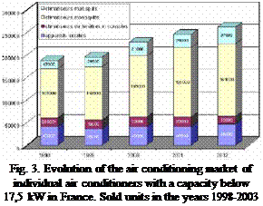
The European Air Conditioning (AC) market has grown rapidly during the last 5 years. The size of AC markets in the seven major European countries (France, Germany, Greece, Italy, Russia, Spain and the UK) expanded from some 2.4 million sold units in 2000 to 5 million sold units in 2004. A further breakdown of the European AC market reveals that Italy and Spain are holding the largest market of about 1.4 to 1.7 million units per year (after 2004), followed by France, Greece and UK at 300,000 to 500,000 units each [5, 6].
 |
![image174 Подпись: Fig. 4. Share of air conditioners with different capacities on the overall Italian market in the years 2005 and 2006 [7]](/img/1155/image174.gif) |
For small cooling demands, typically room air-conditioning units or multi-split systems are used, as can be seen from a closer look at the France and the Italian markets can be stated that especially the monosplit units with small capacities are responsible for more than 50% of the overall sold units (see Figure 3 and 4). Application areas for these systems are mainly in smaller buildings such as the trade and residential sector and small office buildings where in the past mainly local solutions were used.
 |
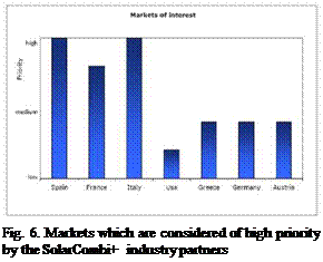 |
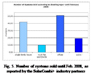
However, small chiller systems have an increasing market share in many European countries. These smaller buildings are seen as the most promising target market for solar combi plus systems, which offer a central chiller system powered by solar heat (see Fig.5). The survey among the industrial participants of the SolarCombi+ project also showed that they see the most interesting markets for their Solar Combi+ systems in Spain, Italy and France (see Fig. 6).
Only in the middle of March 2008 the system was totally uncovered, the pumps fixed and the pressure reset. From that time on, the monitoring process has been more conclusive in the diagnosis of the performance of the STS.
Because the East-facing collector field is hydraulically unbalanced, it reaches a constant value of temperature at least 60° C higher than the totalizing channel. As an example, Fig. 3 shows this behaviour.
The West-facing collector field is well balanced and shows no sign of abnormal behaviour thus the temperature read in the temperature probe is real and representative of the whole west facing collectors.
In April 2008 the STS presented its highest performance level (52%). Since then and because of the leakages previously referred the performance has been steadily decreasing at a pace of around 6% per month (see Fig.4).
|
Temperature Profile in a Typical Day —West Col. Output —Inlet Temperature —East Col. Output —Outlet
0 1 2 3 4 5 6 7 8 9 10 11 12 13 14 15 16 17 18 19 20 21 22 23 7/06/2008 Fig. 3. Typical temperature profile for the STS |
|
Fig. 4. Evolution of the performance. |
But the system is operating satisfactorily with the right behaviour regarding the two azimuthal blocks of collectors. Fig 5 shows the time operation of both blocks through time of pump operation in a typical day of this last monitoring period. East sector begins first in the morning, then there is a period in the central part of the day with both sectors operating simultaneously and finally, in the last period of the day, only West sector is in operation.
Fig 5. Pump relays vs Flow
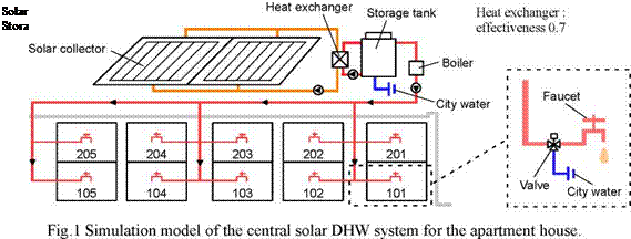 |
The simulated building is an apartment house of two storied with 10 housing units. The central
type of DHW supply system was assumed, which composed of solar collector units, a storage tank and a boiler on the roof as shown in Fig.1. As the simulation result of the past study [1-3] showed that the efficiency of the DHW supply system is not strongly affected by the tilt angle and the azimuth of the collector when the tilt angle is from 20 to 40 degrees and the azimuth is from -15 to 15degrees (0 degree means to face to south). In this study, it is designed that the azimuth of the collector is faced to south and the tilt angle is 30 degrees.
|
Collector area [m2] |
|||||
|
20 |
30 |
40 |
50 |
||
|
0.5 |
A20V0.5 |
A30V0.5 |
A40V0.5 |
A50V0.5 |
|
|
Storage |
1.0 |
A20V1.0 |
A30V1.0 |
A40V1.0 |
A50V1.0 |
|
tank |
1.5 |
A20V1.5 |
A30V1.5 |
A40V1.5 |
A50V1.5 |
|
volume |
2.0 |
A20V2.0 |
A30V2.0 |
A40V2.0 |
A50V2.0 |
|
[m3] |
2.5 |
A20V2.5 |
A30V2.5 |
A40V2.5 |
A50V2.5 |
|
3.0 |
A20V3.0 |
A30V3.0 |
A40V3.0 |
A50V3.0 |
|
Table 1 Simulation cases of the solar DHW system for the apartment house. |

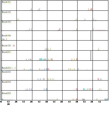 „ 30
„ 30
.E 20 1 10 “ 30
.£ 20 1 10 “ 30
.£ 20 1 10 “ 30
.£ 20 1 10 “ 30
.E 20 1 10 “ 30
.E 20 1 10 “ 30
.E 20 1 10 “ 30
.E 20 S 10 “ 30
.E 20 1 10 “ 30
.E 20 1 10 “ 0
Fig.2 DHW supply profile of 10 housing units in the simulation (Case A DHW supply).
|
Table 2 Simulation cases of DHW supply rate for a housing unit. Simulation cases
|
 |
||||||||||||||||||||||||||||||||||||||||||||||||||||||||||||||||||||||||||||||||
|