Как выбрать гостиницу для кошек
14 декабря, 2021
E. Yandri1* N. Miura1, T. Kawashima1, T. Fujisawa1, M. Yoshinaga2
1 Solar Energy Research Group, Department of Vehicle System Engineering, Faculty of Creative
Engineering, Kanagawa Institute of Technology, 243-0292 Atsugi, Japan
2Department of Architecture, Faculty of Science and Technology, Meijo University, 468-8502 Nagoya,
Japan!
Corresponding Author, yandri@ctr. kanagawa-it. ac. ip
Solar energy can be converted into electricity with Photovoltaic cells and to heat with solar collectors. Especially for solar collectors, the heat collected can be utilized for both water heating and space heating applications. Solar collector researches for space and water heating has been developed and resulted many interesting designs, from simple thermosyphon systems with low maintenance to automatic operation systems which are depended so much with mechanical and electrical properties like pumps, valves, sensors, etc. Recently, a device which transfered heat from the hot reservoir near the top to the cold reservoir at the bottom was invented by Ipposhi et. al [6], called as the ITMI model. As same as the ITMI model was constructed and tested. We improved the ITMI model by proposing the IMT model. The first report was presented in SWC 2007 by comparing the performance of ITMI model and IMT model. The current experiments are completed with a digital flow mater of vapor in order to be able to calculate the heat energy transported. Some experimental parameters are varied in order to know the optimal operating condition for this IMT model. Heat input is varied for 100, 200, and 300W. Inclination angle between evaporator and top heat storage is varied for 0, 5, and 100. Level of heat store in the top heat storage are varied for 20, 110, and 200mm. Result shows that this IMT model can work better for all heat input (100, 200, 300W), and for all heat store in the top heat (20, 110, and 220mm) with inclination angle of 00, 50, 100. This model could be more interesting for water and space heating applications as more ecological approach.
Solar energy can be converted into electricity by Photovoltaic cells, heat by solar collectors, and both electricity and heat by hybrid photovoltaic and thermal (PV/T) panels. The collected heat can be used for Space Heating and Solar Water Heating (SWH). A typical SWH system is a combination of solar collectors, an energy transfer system and a thermal storage system. SWHs are also characterized as open loop system (direct) which circulates potable water through the collectors and closed loop system (indirect) which uses antifreeze heat-transfer fluid such as polypropylene glycol to transfer heat from the collector to the potable water in the storage tank [2]. Depend on the way to circulate the working fluid, SWHs are divided into active system which uses
a pump to circulate the working fluid such as water or polypropylene glycol through the collectors and passive system which circulates the working fluid naturally by the effect of the gravitational force [2]. The passive system calls also thermosyphon which means the heat transport device that can transport a large amount of heat using body forces (gravitational and centrifugal forces). Thermosyphon has a great advantage because of no electrical energy and simple structure. That is why, the thermosyphon researches are not intended for SWH application only, but for many applications. Thermosyphon was studied as an alternative liquid cooling technique in which heat is transferred as heat of evaporation from evaporator to condenser with relatively small temperature difference [3]. Thermosyphon radiator used for domestic and office heating was studied and its performance has been tested with Freon 11, acetone, methanol and water as working fluid [1]. A model of the two-phase flow and heat transfer in the closed loop two phase thermosyphon (CLTPT) involving co-current natural circulation, which is focus for electronics cooling that exhibit complex two-phase flow patterns due to the closed loop geometry and small tube size [4]. The main reason to develop a thermosyphon with a heat source near the top and heat sink at the bottom is to solve weight problem when a thermosyphon installed on the roof [7].
M. Albaric1*, J. Nowag and P. Papillon1
1 CEA, LITEN, INES 50 avenue du Lac Leman, 73377 Le Bourget du Lac, France.
* Corresponding Author, mickael. albaric@cea. fr
Solar energy of today’s solar combisystems provides nearly 20 to 50 % of the total heat demand of a modern standard single family house, depending on climatic conditions. The European market offers a huge variety of solar combisystems and up to now no uniform standard exists that can prove the thermal performances of systems. The system design with its control algorithms plays a very important role and has to be considered carefully. It is obvious that the performance of solar combisystems can vary with different climate conditions and varying building typologies. The focus of this work lays on the choice of the weather data for a 12 test days which allows an annual prediction of the auxiliary energy used. They have to be chosen from a reference weather data for a specific climate zone. Solar irradiation and ambient temperatures should closely correspond to the curves of an annual weather cycle.
Keywords: Solar CombiSystem, performance evaluation, global approach, test lab
Although the European solar thermal market for single and multifamily houses offers today many efficient and reliable products, there is still a high need in system optimization. It is particularly the case for solar combisystems, used for space heating and domestic hot water preparation, in which many individual designs with different control strategies entered the market during the last two decades. For a long time, it has been difficult to determine an accurate performance rating for those systems, and even more difficult to compare them, because there were no common definitions of terms or standard test procedures for that type of system. For the establishment of that fast increasing market and a sustainable further development, the existence of uniform standards, recognized by the whole solar industry, is very important.
To contribute to the national and European research needs, the French National Institute for Solar Energy ‘Institut National de l’Energie Solaire’ (INES) is setting up a new test facility in its laboratories. The objective is to develop a methodology for a 12-day performance test, which allows an annual prediction of the auxiliary energy used and therefore a statement on the energy savings during one year.
Several methods have been developed that are briefly described below.
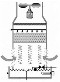
The open loop evaporative cooling tower consists of a shell containing packing/fill material with a large surface area. Nozzles arranged above the packing, spray and distribute heated cooling water from the condenser evenly onto the packing. The water trickles through the packing into a pond from which it is pumped back to the condenser. The water is cooled by air, drawn or blown through the packing by means of a fan. The air flow, which is either in counter-flow or cross-flow to the water flow, causes some of the water to evaporate. The evaporated water is continuously replenished by make-up water. Evaporation however also increases the concentration of TDS (Total Dissolved Solids) in the cooling water. Blow-down of the cooling water is therefore required which is replenished by additional makeup water to dilute and to maintain concentration levels within acceptable limits. It is possible to cool the water below the ambient dry bulb temperature using a cooling tower, as the wet-bulb temperature determines the degree of cooling. An approach of 4°C can still be achieved economically, which is the difference between the water outlet temperature and the ambient wet-bulb temperature [4].
The cooling tower was simulated with the TRNSYS Type 51 b, which models the performance of a multiple-cell counter-flow or cross-flow cooling tower and sump. To employ this Type the user has to enter two coefficients, used in the mass transfer correlation [10]. Although these coefficients are usually difficult to obtain, in the present case they were provided by a cooling tower manufacturer.
The physical parameters used in the cooling tower Type are:
• Maximum cell flow rate = 3800 m3/h
• Fan power at maximum flow rate = 0.33 kW
• Mass transfer constant, c = 2,28

![]() Fig. 3. Open loop wet cooling
Fig. 3. Open loop wet cooling
The selected TRNSYS Type is particular useful and simplifies the method of solution when compared to more conventional numerical procedures. As the Merkel method, this approach is based on the following simplifying assumptions:
• The Lewis factor relating heat and mass transfer is equal to 1;
• The air exiting the tower is saturated with water vapor and it is characterized only by its enthalpy;
• The reduction of water flow rate by evaporation is neglected in the energy balance.
Because of these assumptions, however, the Merkel method does not accurately represent the physics of the heat and mass transfer process in the cooling tower fill.
The method of Poppe, developed in the 1970s, does not make the simplifying assumptions of Merkel. Predictions from the Poppe formulation result in values of evaporated water flow rate that are in good agreement with full scale cooling tower test results. In addition, the Poppe method predicts the water content of the exiting air accurately [11]. An EES code exploiting the Poppe method for a wet cooling tower is being developed and will be employed in future works.
4.1 Overnight temperature drop in December
Results showed that although Flat No. 3 — the most conservative case — had the highest average water temperatures, the overnight thermal energy losses from the solar tank were the least, as shown in Figure 6. Again, this is a proof of good management of hot water, since the users opted to partially fill
 |
 |
the tank with water during the winter months, to counter-balance the lower availability of solar energy. This action had also contributed towards lowering the overnight temperature drop, since there was less volume of water in the tank when compared to other flats. From this graph, one also concludes that it is important for the solar tank to reach a considerably high afternoon temperature in winter (say 45 or 50 °C), so that after loosing energy at night, the water temperature would still be warm enough in the morning, without resorting to back-up electric heating.
Fig. 6. Overnight temperature drop and average hot water temperatures in the solar tanks in December.
The project is divided into 5 major work packages covering all the aspects of technology dissemination like training, test methods development, in-situ monitoring, standardisation, implementation of public policy, and systems development.
2.1. Qualitative evaluation of combisystems
Until now solar combisystems sold on the market are only partly prefabricated systems, most of them are still consisting of quite a number of components which need to be put together by the installer on the construction site. Also, several controller settings of one or more controllers (e. g. solar controller, boiler controller, space heating controller) often need to be done in a correct way to start and run a solar heating system. Therefore there is a risk to make mistakes during installation or when doing the controller settings.
This work package should help to find the key hurdles which can cause less advantageous installed solar heating systems. The learned lessons of this work package should help to improve the designs of prefabricated solar heating systems and to improve the educational activities for professionals.
Based on a selection procedure with different boundary conditions a typical distribution of different system types and products was chosen in cooperation with solar industry. At least 50 systems will be evaluated.
In parallel to the qualitative evaluation of combisystems, the manufacturer datasheets and documentation available in the different countries are collected in order to have a first technical evaluation. This technical evaluation together with the qualitative evaluation will allow preparing the first recommendations regarding the design and the installation of solar combisystems.
A first draft for the evaluation procedure has been written and will be improved during the qualitative evaluation procedure. This evaluation procedure will be available on the CombiSol website.
The measurements started in August 2004. Not all the energy quantities mentioned in section 3.1 were measured during the whole measuring period. A constant energy quantity of 10.67 kWh per m3 natural gas is assumed.
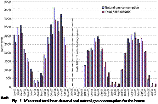
The total heat demand of the house, that is: Space heating demand + domestic hot water consumption + heat loss from circulation pipe, and the natural gas consumption month by month appear from figure 5. Both the heat demand and the natural gas consumption are much lower after the installation of the solar heating system than before. The reasons for the reduced natural gas consumption are:
• The decreased heat demand due to warm weather in the autumn of 2006, in 2007 and in 2008.
• The new energy system with solar collectors and an improved natural gas boiler.
 |
The difference between the natural gas consumption and the total heat demand in the winter months is lower after installation of the solar heating system than before. In the spring, summer and autumn the natural gas consumption is lower than the total heat demand after installation of the solar heating system. Before installation of the solar heating system the natural gas consumption is, for all months, higher than the total heat demand.
Figure 6 shows the measured utilization of the natural gas as a function of the total heat demand month by month. The utilization of the natural gas is defined as: (space heating demand + hot water consumption + heat loss from circulation pipe)/natural gas consumption. The utilization of natural gas is strongly increased by the solar heating system, especially for low heat demands. Further, the utilization of natural gas after installation of the solar heating system is much higher in the sunny spring than in the less sunny autumn.
|
Fig. 6. Utilization of the natural gas as a function of the total heat demand. |
Based on the total monthly measured heat demand and the curves of figure 6 it is possible to estimate the natural gas consumption for the house for all months without and with the solar heating system, if only the heat demands are measured. Consequently, the natural gas savings for the house achieved by the solar heating system can be determined for all months when the total heat demand is measured.
The measured heat demand, natural gas consumption and heat produced by the solar collectors are shown in table 1 for a year without the solar heating system installed, 2005, and for a year with the solar heating system installed, 2007.
Table 1. Measured energy quantities.
|
Period |
Space heating demand |
Domestic hot water consumption |
Heat loss of circulation pipe |
Total heat demand |
Natural gas consumption |
Solar heat |
|
2005 |
17970 kWh |
3280 kWh |
300 kWh |
21550 kWh |
25130 kWh |
— |
|
2007 |
16300 kWh |
2610 kWh |
160 kWh |
19070 kWh |
18790 kWh |
2580 kWh |
The yearly natural gas savings estimated month by month as described above are 3400 kWh for 2005 and 3800 kWh for 2007. Further, based on measurements, yearly electricity savings of 200 kWh are estimated. The yearly total energy savings are therefore estimated to 3600 kWh for 2005 and 4000 kWh for 2007, corresponding to yearly energy savings of 530-590 kWh per m2 solar collector.
Figure 7 shows for 2007 quantities for the monthly total heat demand, the natural gas savings due to the solar heating system and the solar heat produced by the solar collectors. The heat demand is high in the winter and low in the summer. The monthly natural gas savings and the solar heat production are higher in the spring months than in the other months of the year.
|
0 |
Fig. 7. Measured total heat demand, natural gas savings and solar heat for 2007.
The energy savings will vary from year to year. In years with a high heat demand and a high solar radiation, especially in the spring, the energy savings will be high. In years with a low heat demand and a low solar radiation, especially in the spring, the energy savings will be low. The yearly heat production of the solar collectors is in 2007 about 65% of the yearly energy savings.
Measurements of the heat demand and energy consumption in a demonstration house before and after installation of a new developed solar heating/natural gas heating system based on a condensing natural gas boiler and 6.75 m2 solar collectors have been carried out.
Based on the measurements the energy savings by the solar heating system are for two years estimated at 3600 kWh and 4000 kWh per year, corresponding to 530-590 kWh/m2 collector per year. The energy savings will vary from year to year. In years with a high heat demand and a high solar radiation, especially in the spring, the energy savings will be high. In years with a low heat demand and a low solar radiation, especially in the spring, the energy savings will be low. The yearly heat production of the solar collectors is in 2007 about 2/3 of the yearly energy savings.
[1] S. Furbo, J. M. Schultz & A. Thur (2007). Energy savings for a solar heating system in practice. ISES Solar World Congress Proceedings, Beijing, China.
[2] T. Larsson (2000). Enkatundersokning om energibesparing och drift med solfangare. Orebro University, Sweden, report 00:00.
[3] A. Thur, L. J. Shah & S. Furbo (2006). Energy savings for solar heating systems. Solar Energy Vol. 80, Issue 11, pp. 1463-1474.
[4] S. Furbo, L. J. Shah,. C. Holm Christiansen & K. Vinkler Frederiksen (2004). Kedeleffektiviteter for oliefyr og naturgaskedler i enfamiliehuse. Department of Civil Engineering, Technical University of Denmark, report R-072.
[5] A. Thur (2007). Compact Solar Combisystem. High Efficiency by Minimizing Temperatures. Department of Civil Engineering, Technical University of Denmark, report R-160.