Как выбрать гостиницу для кошек
14 декабря, 2021
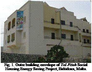 |
The Housing Authority took the initiative to build the first Energy Saving Social Housing Project at Tal-Ftieh, Birkirkara, Malta. This was mainly comprised of two adjacent blocks with a total of 10 apartments and 1 showroom. A workgroup of experts were appointed to prepare a number of energysaving measures for this project [3] . Figure 1 shows the external building envelope with some of the implemented energy-saving measures such as, louvered windows, double-glazing, shading and solar applications. Following the success of this project, the Housing Authority decided to adopt a policy of energy saving for all its future buildings. These include thermal insulation on roofs and walls, doubleglazing, louvered windows, solar water heaters, and an underground rain-water reservoir [4] .
 |
specifications. This was followed by commissioning of the systems and a one-to-one meeting with the users, to explain the system for them and ask them to take readings from the electronic display in the morning and the afternoon. This data was then collected on a monthly basis and analysed accordingly.
For each hydraulic scheme, different size of the collector area (from 5m2 to 25 m2) and heat store volume (from 400 litres to 1500 litres) were used. In order to know if the optimised test sequence is also suitable for other reference buildings (SFH30, SFH100) further simulations with varying solar combisystem sizes were carried out.
|
Storage volume (l) |
Collector area (m2) |
Auxiliary consumption for heating and domestic hot water based on : |
Difference (%) |
|
|
Annual simulation (kWh) |
Test sequence and extrapolated to an annual value (kWh) |
|||
|
400 |
8 |
12531 |
12574 |
0.34 |
|
400 |
10 |
12289 |
12160 |
-1.06 |
|
600 |
8 |
11855 |
11772 |
-0.7 |
|
600 |
12 |
11263 |
11054 |
-1.89 |
|
800 |
12 |
10943 |
10647 |
-2.78 |
|
800 |
16 |
10458 |
10221 |
-2.31 |
|
1000 |
12 |
10779 |
10510 |
-2.56 |
|
1000 |
20 |
9835 |
9660 |
-1.81 |
|
1500 |
20 |
9507 |
8931 |
-6.45 |
|
Table 3. Comparison of the auxiliary consumption for an annual simulation, and for the prediction based on the result of the test sequence (The results in the table are related to the Zurich climate conditions and a single family house with a 60 kWh/m2.year space heating demand). |
 25 000
23 000
21 000 A
19
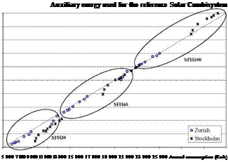
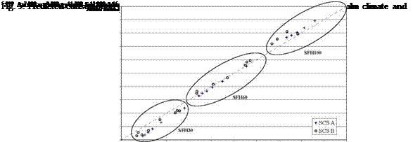
Fig. 3. Predicted consumption with the test sequence versus annual consumption for Zurich climate and the
reference Solar Combisystem.
Although the test sequence was optimised for the SFH60 building, the results from building type SFH100 and SFH30 are promising. Moreover the criteria chosen to select the days are working for different climates.
For Zurich climate it can be seen that predicted and annual simulation values are close to each other. Best results can be achieved in case of building type SFH100. On the other way for Stockholm climate best results are obtained for building type SFH60.
1 Department of Civil Engineering, Technical University of Denmark, Brovej, Building 118, DK-2800 Kgs.
Lyngby, Denmark
2 AEE INTEC, Feldgasse 19, A-8200 Gleisdorf, Austria
* Corresponding Author, sf@byg. dtu. dk
In July 2006 a new developed solar heating/natural gas heating system was installed in an old one family house in Denmark. The new system is based on 6.75 m2 solar collectors and a condensing natural gas boiler. Before the installation of the solar heating system, the house was heated by a non condensing natural gas boiler.
The heat demand, the electricity consumption for the energy and heating system as well as the natural gas consumption were measured before and after installation of the solar heating system. Based on the measurements the yearly energy savings of the solar heating system are estimated to 3600 kWh for 2005 and 4000 kWh for 2007, corresponding to 530-590 kWh/m2 collector per year. The energy savings will vary from year to year. In years with a high heat demand and a high solar radiation, especially in the spring, the energy savings will be high. In years with a low heat demand and a low solar radiation, especially in the spring, the energy savings will be low. The yearly heat production of the solar collectors is in 2007 about 2/3 of the yearly energy savings.
Keywords: Solar combi systems, energy savings, measurements
Only few investigations on energy savings for solar heating systems in practice have been carried out, [1]. This is remarkable since most solar heating systems are installed with the aim to save energy. The reason for the few investigations is that it is extremely difficult to measure/document the energy savings for solar heating systems in practice.
In order to determine the energy savings, seven energy quantities/efficiencies must be considered.
Before installation of the solar heating system:
• Utilization of energy for the energy system.
• Electricity consumption for the energy system.
After installation of the solar heating system:
• Net utilized solar energy of the solar heating system.
• Saved energy by turning off the auxiliary energy supply system during the summer.
• Utilization of energy for the auxiliary energy supply system.
• Electricity consumption for the auxiliary energy supply system.
• Electricity consumption for the solar heating system.
Further, to make the determination even more difficult, the above mentioned energy quantities and efficiencies and thereby also the energy savings are influenced by the heat demand and hot water
consumption, which will vary from year to year due to weather variations, variations of user habits and due to changes of the hydraulics of the energy system.
A Swedish investigation of solar heating systems, based on questionnaires filled in by home owners, showed unexpectedly high energy savings for solar heating systems in practice [2]. Also unexpectedly large variations of the energy savings were reported. Solar heating systems with collector areas between 4 m2 and 25 m2 were included in the investigations. The reported energy savings ranged from 0 kWh per m2 to 2750 kWh per m2. The average collector area of the investigated systems was 11 m2, and typical energy savings ranged from 650 kWh per m2 collector to 900 kWh per m2.
A theoretical investigation showed that the energy savings of solar heating systems are strongly influenced by the efficiency of the energy system prior to installation of the solar heating systems
[3] . Especially the efficiency during the summer period is of great importance.
An investigation of new natural gas boilers and oil fired burners installed in one family houses without solar heating systems showed unexpectedly low utilizations of natural gas and oil in the summer and in periods with low heat demands [4]. This is of great interest in countries, such as Denmark, where oil and natural gas are often used as primary energy sources in houses, where solar heating systems are installed. A condensing and a non condensing natural gas boiler as well as a non condensing oil fired burner were included in the investigations. In spite of high yearly utilizations of natural gas and oil between 80% and 95%, the utilization of natural gas/oil decreased to values between 50% and 80% for the boilers/burner in the summer months. In the 5 summer months May-September the energy loss defined as the oil/natural gas consumption minus the space heating demand minus the hot water consumption was about 1000 kWh for the oil fired burner and the non condensing natural gas boiler and about 500 kWh for the condensing natural gas boiler. These energy quantities can easily be saved by well performing solar heating systems.
We designed the system with ultra low power operation in mind with the controller designed from scratch, not as a modification to a mains powered controller. Pump switching is done using a thyristor rather than a relay in order to save energy.
One of our early design specifications was that the controller should not require battery replacement during a lifecycle in excess of 20 years operation. Our innovative controller therefore utilises an electricity store via super capacitors with 500,000 charge / discharge cycles (rechargeable batteries offer around 600 cycles only). The super capacitors are charged in the early morning daylight when the solar thermal system is most likely to be cool and there is insufficient power available to begin PV pumping around the system. We also use day / night mode detection logic to reduce power consumption by increasing sensor interrogation time at night. The super capacitors offer over 30 hours display backup time and over 7 days program backup time without any power available. The controller will switch up to 1A DC and integrates internal self-resetting overload protection. It is suitable for operation with 18 and 36 cell PVs, nominally 11-21V open circuit voltage up to 20W with the facility to increase this if necessary. There is also an alternative option for low voltage DV power supply operation.
Our innovative controller uses an integral microprocessor together with three sensors (PT1000 sensor for panel) and a temperature display which can be top of cylinder temperature (default) or
displays from all three sensors. The operation utilises both primary and secondary logic.
Primary logic offers:
• Differential control
• ON DT of 4-15C
• OFF DT = from 2 degrees below ON DT to 2 degress
• Pump off overrun time can be set between 0 seconds and 300 seconds
Whilst secondary logic offers:
• What to do at high cylinder temperatures? — 3 options are
i. Pump on (always used with Solartwin)
ii. Pump off (for most conventional solar thermal)
iii. Pump remains differential (occasionally used with conventional solar thermal)
• The temperature to implement secondary logic can be selected between 65 and 85C
The technical specification of the controller was a primary concern and with superior specification in mind we developed the unit with the following specification:
• Temperature Range : -30C ~ +200C in panel and 0C to 105C on cylinder
• Temperature Sampling Time : 30 Seconds by day but slower by night
• Sensor types
i. TP Sensor : PT1000 ( -30C ~ +200C ), silicone coated 12m / 15m black or yellow coated
ii. TA Sensor : 103AT2 ( 0 C ~ +110C ), PVC wire coaxial black or red coated
iii. TB Sensor : 103AT2 ( 0 C ~ +110C ), PVC wire coaxial black ort blue coated blue
• PV External Power 18 — 36 Cell PV, 5-30W, all within these total constraints, max 24V DC AND max 1.7A, whichever is lower.
• Pump Control Output ON/OFF. (Variable speed comes from PV output).
• Memory with Power Saving Design
• Housing materials: Main box is ABS.
• Programme input via 3 buttons which are inside the box
• Energy storage 2 x 50F super-capacitor. (500,000 recharge cycles typical)
• Switch is a mosfet max 60V 3,7A peak 25A
• Self-resetting fuse max current is 1.5A-1.8A.
• IC voltage tolerence 4-24V normal, or temporarily (under 1 second) at 40V
The heating system for a small house with the ground plan 50 m2 and the fit up attic was constructed. It consists of a 2,7 m2 open thermal heat collector designed for heating of swimming pools [6]. The heat collector surface is protected in a distance of 10 cm from the absorbing area on the front side with the transparent plastic sheet and on the back side with plywood board. The lower and upper parts of the heat collector are opened, so that the air can freely flow in the interstitial space.
The heat pump, type GvP-25 [7], is dimensioned for the delivery of 2,5 kW heat for the floor heating. It is connected to the heat collector via flat heat exchanger. The heat exchanger is placed between the throttle valve and 60m long copper tube through which flows the expanded heat pump fluid. The tube is placed horizontally at the bottom of the excavated pit 4 x 8 x 1 m in a pattern depicted in Fig. 1 (loop 5). The distance between the parallel sections of the tube is 50 cm. The pit is filled with the excavated earth to the half of the depth and a second tubing system is laid at this height. It consists of two 32 mm diameter polyethylene tubes, situated along the long sides of the pit. These tubes are connected with 20 parallel tubes 16 mm i. d. (Fig 1, loop 9). This tubing system is used for warming the soil in the pit with excess heat from the SHC.
20 cm above this pipe system is laid drainage pipe system with a pattern similar to the previous one (position 12 in the Fig. 1). The pit is then filled to the full height of 1 m with the soil. The drainage pipe system distributes the rain water collected from the roof of the house.
Temperatures at critical parts of the system, insolation and relative humidity of the air are measured every third minute. Five measurements are averaged and the results are stored in a data logger [8]. 10 m from the edge of the pit, 1 m below the northern part of the house, is situated the sensor measuring the natural variations of the soil temperature. Temperatures are measured with Pt 100 sensors. Solar irradiation is measured with the pyranometer Kipp & Zonen, model CM3 [9] and the relative humidity with the EMS 33 sensor [8].
Solar Energy Research Center SERC, Hogskolan Dalarna, 78188 Borlange, Sweden
Corresponding Author, jip@du. se
A feasibility study for combining solar thermal plants with small scale 0.5-2 MWth mobile district heating plants under north European conditions was done. The study was done from a heat service company point of view, trying to come up with generally applicable scenarios rather than case studies. It was found that if the saved fuel is mainly pellets, without subsidies it is difficult to find economically feasible payback periods within the plants estimated lifetime, even with moderate pellet price increases. With oil as saved fuel the feasible payback periods range between 10-20 years with an estimated 5% annual oil price increase. The costs of moving the solar plant to another locations were also considered. A rough estimation of these costs resulted in a prolonged payback period of 3-6 years, which is considered too long regarding the general plant payback periods.
Keywords: district heating, feasibility, solar thermal, pellets
Selling heat is a business concept (heat service company) for which the market has grown rapidly in the Finland and Sweden during the last decade in the scale of 0.5-2 MWth peak power district heating (DH) plants. In this concept the heat service company sells heat to customers, so that they own and operate the heat production plant and the customer gets only an invoice for used heating energy, as opposed to the heat consumer traditionally owning the heating plant in this scale. With probably the recent development in energy prices as a reason, the trend is such that customers also more often want relatively short term (5-10 years) heat delivery contracts, which gives them a chance to negotiate new contract terms or switch to another heat provider if the offered energy price is not satisfactory. Under these conditions the heating plant should be “mobile” so that it can be moved to another location without too high costs. A feasibility study to find out general boundary conditions for the economic feasibility of combining solar thermal plants with small scale DH networks in the above mentioned concept in Finland and Sweden is presented.
Monitoring started at the end of July 2006, thus results are presented for August 2006 onwards. The heat flows in all hydraulic loops have been measured with calibrated sets of flow meters and temperature sensors. The air flow through the stove has not been measured. Instead, the measured values from the lab for the stove efficiency have been used to calculate the flue gas heat losses based on measured pellet use. Heat transferred from the stove directly to the building was
calculated as the balance of the pellet energy and the flue gas losses together with the measured heat transferred to the water loop. Two separate electrical meters were installed to log the electricity consumption of the system and the electrical auxiliary heater. A simple pyranometer has been used to measure the solar radiation. A number of temperature sensors have been installed to give additional information about the status of the system components and the functioning of the system. Figure 2 shows the REBUS system schematic with sensor positions. The electrical meters and the pyranometer are not shown. The data were logged using a Campbell CR10 data logger with attached multiplexers. Average data values were stored with an interval of one minute.
The owner has kept good records of bought energy for the year previous to the installation, and these values are presented in some of the figures. The amount of wood used was estimated by the user and the tiled stove was assumed to have an efficiency of 50%.
The solar-assisted absorption cooling system simulated in this work is represented in the schematic diagram of Fig. 1. The TRNSYS environment has been employed to set up the simulation [6]. TRNSYS has a standard library of components that includes most of the elements usually employed in HVAC installations.
|
|
The absorption chiller has been simulated with the model presented in [7], which is able to reproduce the typical behaviour of a commercial single stage LiBr-H2O chiller. The solar collectors considered are of the flat plate type, with special anti-reflective glazing. Their second order efficiency curve is obtained from the standard certification performed by the Solartechnik Prufung Forschung Institut.
To simulate the air-cooled heat exchanger performance a set of equations is written and solved by means of the engineering equation solver (EES), developed at the University of Wisconsin, Madison. TRNSYS is then linked to this external programme and all the variables of interest are dynamically exchanged between the two. The behaviour of the cooling towers is simulated thanks to a standard component of TRNSYS which relies on performance data supplied by the user.
Four out of ten solar systems were monitored for a period ranging between 5 months and 2 years, starting in April 2005 up to December 2007 [6] . One of the targets was to calculate the efficiency (n) of the solar system as a whole. This may be defined as:
П = — (Equation 1)
Hincl * A
 Useful output energy (hot water) = m*c*AT
mass of hot water usage = volume of water * density of water
specific heat capacity of water = 4.2 kJ/kg K
difference in water temperature before and after sunshine during one day in-plane solar radiation (kWh/m2/day) area of the collector (m2)
Since solar radiation could not be measured on site, data was taken from the nearby Institute for Energy Technology (8 km away) and used for this project. Modelling was also used to calculate the expected solar radiation at the inclination of the tubes (45° to the horizontal), since the available data at the Institute was at an inclination of 36° to the horizontal. Figure 3 shows the comparison between the calculated and measured data at an angle of 36°, which proved to be sufficiently accurate, with a maximum difference of ±8% for clear skies.
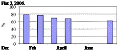
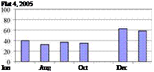
Figure 4 shows a compilation of the efficiency results for four solar systems. Although all apartments had the same number of occupants (2 adults each), the efficiency of the solar systems varied dramatically between 30 and 80%. This was mainly caused by the different lifestyles and the amount of hot water consumed. Higher efficiencies implied that hot water was being used in larger quantities, giving the chance for cooler water to absorb more energy from the sun. On the other hand, lower efficiency systems were associated with careful users of hot water. It was interesting to note that all users were satisfied with the performance of their systems and had sufficient hot water without reverting to the electric back-up heater. This was purposely disconnected throughout the data acquisition period.

 100 80
60
O’"
40 20 0 100 80
60
O’"
40 20 0
Fig. 4. Typical monthly efficiencies for 150-litre solar heaters, used by couples in four different apartments.
Consequently, it was concluded that the term ‘Efficiency" could confuse the users to understand the effectiveness of their system, as they would associate low efficiency with bad performance, which was not the case here. A new term had to be introduced to better describe the system’s performance as shown in the next section.
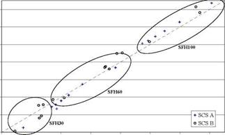
The same test sequences were also tested with two commercial solar combisystems:
• one storing heat within a tank (A in the following figure),
• one using the thermal mass of the building as heat storage (B in the following figure).
13 000
з
s
о
11 000 <5
и
■З
9 000 0и
![]()
![]()
![]()
![]()
![]()
![]()
![]()
![]()
![]()
 |
7 000
These results show that the test sequences developed with the referenced SCS for two climates are also able to predict the auxiliary energy used for commercial systems with different hydraulic and concept design.
For the building type SFH100 where the heat demand is bigger, the difference between the predicted and the annual heat consumption is in the same order than for buildings type SFH60. For the building type SFH30 this difference is bigger.
Moreover the results for the SCS using the thermal mass of the building as heat storage are less precise than for the other.
Based on the CCT approach, the methodology developed at INES can provide test sequence for different climates. These test sequences have been tested, the results obtained for different solar combisystems design (different control strategies and hydraulic layout), different dimensioning characteristics for a same design (collector area and storage volume) and different building heating demands, prove that the methodology is very efficient.
Thanks to this work, it is possible to test for different climate all typologies of solar combisystems, incorporating all the innovations for hydraulic diagram or control strategy. The major aim of the test method is to be able to make an annual prediction of the final auxiliary energy use for the tested combisystem. This is done by extrapolating the 12-day test results to annual performance.
[1] C. Bales, (2002). Combitest _ Initial Development of the AC/DC Test Method, Technical report, IEA Solar Heating & Cooling programme Task 26, http://www. iea-shc. org/task26
[2] D J. Naron, H Visser, (2002). Development of the Direct Characterisation test procedure for Solar Combisystems, fifth draft, Technical report, IEA Solar Heating & Cooling programme Task 26, http://www. iea-shc. org/task26 [3] [4] [5] [6] [7] [8]