Как выбрать гостиницу для кошек
14 декабря, 2021
In the previous subsections, we have listed a certain number of criteria that should fulfill a working fluid to be considered as good fluid for an ORC system. But, the most important thing remaining is to know how could perform the system using a particular fluid in realistic conditions. The easiest and fastest way is to simulate the system using a computer program and a database of thermodynamic properties of the fluid. Using the first and second law of thermodynamics [12], the performance of the system can be evaluated under diverse working conditions for different working fluids.
For simplicity, mass, energy and exergy balance equations for any control volume at steady state can be written respectively as follows neglecting the kinetic and potential energy changes:
|
У m = У m 4-^ out in |
(1) |
|
Q + W = У m hout — У m h. out out n n |
(2) |
|
Eh + W = У E — У E +1 h out n |
(3) |
Where the subscriptions in and out represent the inlet and exit states, m is the mass flow rate,
Q and W are the net heat and work inputs, h is the enthalpy, Eh is the net exergy transfer by
heat and I is the rate of irreversibility. From the above equations, the heat input or rejected, the pump work, the turbine work and many other derived characteristics as thermal efficiency, exergy efficiency and exergy destruction are obtained. Parametric studies performed at various operating conditions for different potential working fluids then show us which one yields better performance.
Most authors while selecting a working fluid for an organic Rankine cycle consider the cycle thermal efficiency as the most determinant parameter. This is not for sure the best way. A very efficient plant can be bulky, expansive and unsafe. On the other hand, it is not easy to find an ideal fluid that fulfils all the desired criteria mentioned in the previous section. One may have low vapour specific volume, good heat transfer properties but present a low critical temperature for example. Since, the ideal working fluid does not exist a compromise should be found among the desired criteria. A general methodology is proposed here. It comprises three steps [1, 13]: (1) data collection, (2) data analysis and (3) decision. At the first step, the operating conditions are set and all the data: thermophysical, safety, environmental and calculated properties concerning different candidates are collected. The data are then analyzed at the second step. At this phase, the criteria are classified starting from the most critical ones and the process is done sequentially. At each sub-step, all the fluids are screened using the criterion and before going to the next criterion, the fluids are put in two groups: those which fulfil the criteria and those which do not. At the last step, the best fluid should come out followed by some alternatives. Usually, it is not easy to make up the decision, and some authors propose to combine several criteria into one that could be used as an “objective criterion” [14]. Different steps described above are illustrated in Table 5.
|
Table 5: steps involved in the selection of the working fluid
|
4. Conclusion
The choice of the most suitable working fluid for a peculiar application is a critical step when designing an organic Rankine cycle system. It is not easy to find a working fluid that could
fulfill all the characteristics of an ideal working fluid. Various criteria that should satisfy a good fluid were given. These include: appropriate critical parameters, moderate cycle pressures, low specific volumes, high efficiency, non-toxicity, non-corrosiveness, easy purchase, non-ozone depleting and no contribution to the global warming.
We attempted in this work to propose a general methodology for selecting working fluids.
The selection according to this methodology can be made in three steps: (1) data collection,
(2) data analysis and (3) decision.
[1] O. Badr, S. D Probert and P. W. O’Callaghan, Selecting a working fluid for a Rankine-cycle engine, Applied Energy 21 (1985) 1-42.
[2] W. B. Stine and M. Geyer, Power cycles for electricity generation, In power from the sun, 2001. <http://www. powerfromthesun. net/chapter12/chapter12.new. htm> [July 2008]
[3] R. L. Powell, CFC phase-out: Have we met the challenge? Journal of Fluorine Chemistry 114 (2002) 237-250.
[4] G. Angelino and P. Colonna di Paliano, Multicomponent working fluids for organic Rankine cycles (ORCs), Energy 23 (1998) 449-463.
[5] M. J. Lee, D. L. Tien, C. T. Shao, Thermophysical capability of ozone-safe working fluids for an organic rankine cycle system, Heat Recovery Systems & CHP 13 (1993) 409-418.
[6] V. Maizza, A. Maizza, Working fluids in non-steady flows for waste energy recovery systems, Applied Thermal Energy 16 (1996) 579-590.
[7] H. Yamaguchi, X. R. Zhang, K. Fujima, M. Enomoto, N. Sawada, Solar energy powered Rankine cycle using supercritical CO2, Applied Thermal Engineering 26 (2006) 2345-2354.
[8] Ezzat Wali, Working fluids for solar, rankine cycle cooling systems, Energy 5 (1980) 631-639.
[9] L. Calderazzi and P. Colonna di Paliano, Thermal stability of R-134a, R141b, R13I1, R7146, R125 assiociated with stainless steel as a containing material, International Journal of Refrigeration 20 (1997) 381-389.
[10] G. Angelino, C. Invernizzi, Experimental investigation on the thermal stability of some new zero — ODP refrigerants, International Journal of Refrigeration 26 (2003) 51-58.
[11] Kyoto Protocol to the United Nations Framework Convention on Climate Change, United Nations, 1998.
[12] Yunus A. Cengel, Michael A. Boles, Thermodynamics: An Engineering Approach, 4th edition, McGraw-Hill, 2002.
[13] U. Drescher, D. Bruggemann, Fluid selection for the organic Rankine cycle (ORC) in biomass power and heat plants, Applied Thermal Engineering 27 (2007) 223-228.
[14] H. D. Madhawa Hettiarachchi, Mihaljo Golubovic, William M. Worek, Yasuyuki Ikegami, Optimum design criteria for an organic Rankine cycle using low-temperature geothermal heat sources, Energy 32 (2007) 1698-1706.
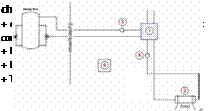
A control system is developed to automatically operate valves and pumps in order to follow the defined strategy either for summer or winter operating modes. The unit is controlled according to the heat demand for space heating or cooling demands and domestic hot water as well. Priority is given to space conditioning. Fig. 3 shows the Hydraulic scheme adopted.
|
Fig. 3. Hydraulic scheme of the trigeneration system installed at Ao Sol office building. |
The CHP is equipped with an integral microprocessor controller that maintains a constant electrical output. The Electricity generated by the CHP Unit is to be consumed on site (not grid connected).
Ahmed Hamza H. Ali1, P. Noeres2 ,C. Pollerberg2* and C. Doetsch2
1 Department of Mechanical Engineering, Faculty of Engineering,
Assiut University, Assiut 71516, Egypt
2 Fraunhofer Institute for Environmental, Safety and Energy Technology UMSICHT,
Osterfelder Strasse 3, 46047 Oberhausen, Germany
* Corresponding Author, clemens. pollerberg@umsicht. fraunhofer. de
Abstract
The synchronous occurrence of solar irradiation and cold demand and its causality led to the development of solar cooling facilities. Previously, a number of prototypes and demonstration plants have been erected world wide. Several techniques and concepts are discussed currently and there is still a high necessity for research and development. But there are also first operational experiences gathered by the existing plants. For the further development of solar cooling and the implementation of these systems into the market, it is important to evaluate and to interpret the available experiences.
Since 2002 Fraunhofer UMSICHT has operated a solar cooling plant on its premises in Oberhausen, Germany. The plant target cold capacity is 58 kWth for space cooling. Most of the motive heat energy is provided by a solar tube collectors field while the backup heat source is the heating system of the institute. The plant also provides solar surplus heat to the institute heating system in spring and in autumn. Furthermore, the plant concept allows the operating mode “free cooling”, which means that the cold capacity is exclusively provided by the recooling unit when the ambient air temperature is low enough.
The proposed paper describes the solar cooling plant and its integration in an existing energy supply network. In addition, it summarises and analyses the operating experiences of the years 2002 to 2007.
Keywords: Solar cooling, free cooling, operational experiences, absorption chiller
In the last years, a number of solar cooling plants were erected to investigate the possibility of using a renewable energy sources for cooling applications and to demonstrate their feasibility. The use of the sun as renewable energy source is particular obvious, because solar irradiation and cooling demand is normally synchronized. Since the year 2002 Fraunhofer UMSICHT has operated a solar cooling plant on its premises in Oberhausen, Germany.
Nowadays, about 100 solar cooling air-conditioning systems are installed in Europe according to [1]. Their primary energy savings potential is estimated between 30-60 %. Balaras et al. reported in [2] that a total of 54 solar air-conditioning projects in Europe are in operation, 33 plants are working with lithium bromide-water (LiBr-H2O) absorption chillers. Single-effect lithium bromide-water absorption chillers are the most popular machine in solar cooling due to its ability to operate at low temperature. There are a lot of publications available dealing with the description and a first assessment of respective cooling plant, but long time operational experiences are rarely seen. Ward and Lof [3] described a first integrated system which provides heating and cooling to a building by use of solar
energy. The plant had been installed in a residential building at Colorado State University. It was designed to cover 60 % of the heating and cooling load of the building. Ward et al. reported in [4] for the Solar House I, where a solar heating and cooling system has been operated and monitored in the duration of August 1st, 1974, to January 13th, 1975. The installation provided 40 % of the cooling load by solar energy. Furthermore, Ward et al. reported in [5] about the possibility to improve the average coefficient of performance (COP) of the cooling system by the use of a cold water storage. Bong et al. describes in [6] a solar-powered 7 kWth absorption chiller in Singapore. The system included heat pipe collectors with a total area of 32 m2, an auxiliary heater, a hot water storage tank, and a 17.5 kWth cooling tower. The overall average cooling power provided was 4 kWth, COP of 0.58 and a solar heating fraction of 39 %, which means 60 % of the driving heat work was provided by the auxiliary heater. In [7] Al-Karaghouli et al. reported the operation results of a solar cooling system which was installed at the Solar Energy Research Center in Iraq. The system is equipped with two absorption chillers with a cold capacity of 235 kWth for each, 1577 evacuated tube collectors and 2 thermal storage tanks of 15 m3. They reported that the daily average solar collection efficiency is 0.49, the COP of the chiller is 0.618 and the solar heating fraction is 60.4 %. In [8] Yeung et al. reports about a solar driven absorption chiller with a cold capacity of 4.7 kWth at the University of Hong Kong. The system included flat collectors with a total area of 38.2 m2 and a 2.75 m3 hot water storage tank. The collector efficiency is estimated with 0.375, the annual system efficiency is 0.078 and the average solar fraction is 55 %. Best and Ortega summarized in [9] the operational experiences of a solar cooling plant from 1983 to 1986 in Mexico. The system consists of 316 m2 flat plate collectors, a 30 m3 heat storage tanks, LiBr-H2O absorption chiller with a cold capacity of 90 kWth and a cooling tower with re-cooling power of 200 kWth. The solar heating fraction reaches 53 % to 75 % and the average COP of the chiller is 0.53 to 0.73. In ref. [10] Syed et al. report about the performance of a absorption chiller with 35 kWth nominal cooling power driven by hot water from flat plate collectors with a size of 49 m2 and a 2 m3 hot water storage tank. The designed cold capacity output of the solar cooling plant is only 10 kWth, so that the daily and period average COP reaches only values from 0.34 to 0.42. Pongtornkulpanich et al. described in ref. [11] the installation of a solar driven absorption cooling system with a cold capacity of 35 kWth in Thailand. The system has a 0.4 m3 hot water storage tank and 72 m2 sized evacuated tube solar collectors filed that delivered yearly an average solar heating fraction of 81 %.
In order to summarize the above cited operational experiences, reported solar driven single-effect lithium bromide-water absorption chillers for space cooling applications have a solar heating fraction from 39 to 95 % and reach COP values ranging from 0.34 to 0.73. This work presents operational experiences over a five years period of such a system. The solar cooling plant is located on the premises of the Fraunhofer institute UMSICHT in Oberhausen, Germany, and belongs to the infrastructure. Ali et al. [12] reported the performance assessment of this plant.
Musbah Mahfoud and Ahmad Bin Marzook
Department of Mechanical Engineering Technology
College of the North Atlantic-Qatar
Abstract
Sun-light is an abundant and infinite source of energy that is currently being overlooked. The sate of Qatar, which is located close to the tropic of Cancer, is well positioned to exploit this potential. The country’s climate is sunny most of the year with temperatures ranging from 12oC to 58oC. In addition to being sunny, the climate is typically hot and humid. To avoid these extreme weather conditions, the population of Qatar depends on enclosed air-conditioned areas and other forms of refrigeration. Since the early 30’s, the country has spent millions of riyals on refrigeration and air conditioning to strive and survive in this climate.
Thus far, the main form of energy used in Qatar has been fossil fuels, a non-renewable energy source. Solar energy, an abundant renewable energy source, is available in the country, but has yet to be exploited. Solar energy has been used throughout the world in various applications such as cars, calculators and heating water, but its use as an energy provider for refrigeration has not been widely investigated. Some household items currently operated electronically can be replaced with solar powered alternatives. Thus, solar energy can reduce cost and save energy if exploited in Qatar.
The direct conversion of sunlight into electricity is a very elegant process that generates environmentally friendly, renewable energy. The purpose of this study was to present a method to attain cooling using solar thermal energy.
In terms of refrigeration, the idea was to investigate the possibility of developing a refrigeration system that depends fully on solar energy. The current project consists of the physical construction of a Solar Refrigeration System. The project involved analyzing, designing and assembling a solar system consisting of (along with other accessories) a laboratory refrigeration unit and a solar panel.
In terms of air conditioning, the objective was accomplished with a parabolic solar reflector and a heat absorption cooling system using ammonia, water, and hydrogen. It is shown that such a system can indeed produce significant cooling using solar thermal energy alone.
A crucial response to the dangers of global warming is the worldwide utilization of solar energy. Solar thermal technology is modular, operated silently and is therefore suited to a broad range of applications and can contribute substantially to future energy needs. From a sustainability perspective, directly using solar energy is attractive because of its universal availability, low environmental impact, and low or no ongoing fuel cost. Solar cooling could be a useful technology in areas of the world where there is a demand for cooling, high insulation levels and no firm electricity supply to power conventional systems.
Solar systems are relevant to Qatar because:
o Ambient temperatures are high through out the year in most parts of the country. Higher ambient temperatures mean more energy is consumed in refrigeration. o Solar insulation is high in most parts of the country. This implies that we have more energy at our disposal.
o There is huge potential demand for refrigeration in rural areas, which are best suited for solar energy based refrigeration systems.
o There is a high potential for cost and energy savings.
Cooling using solar thermal heat was first patented by Shipman1 in 1936. The idea was not applied on a wide scale because the process was relatively inefficient and other forms of energy were cheap and readily available. Erickson and Donald2 have demonstrated recently that there has been a renewed interest in the process. Uli et al3 completed detailed studies on the performance of the bubble pump (the device that drives the process) last year. Erickson and Donald2 presented a large scale application of this process in their paper, which was published during the course of the research for the present work. They mentioned that heat absorption cooling is currently used to cool Cochise Community College in Arizona.
For the development of standardized solar cooling systems it is indispensable to use a system controller for the complete system. The previous solar cooling demonstration and pilot projects are using several single controllers e. g. for the solar thermal system, for the chiller, for the recooler and for the cold or heat distribution, which are together cost intensive and are not always operating optimal together. The alternative was until now an expensive SPS controller which had to be programmed for each single case. Because of that the SolarNext has decided in the year 2007 to develop an own system controller for the whole system (Fig. 2.), which has an influence from the automotive sector and is cheap and system oriented.
|
Fig. 2. chillii® Solar Cooling System scheme (source: SolarNext). |
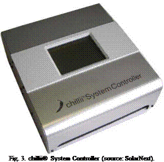
The functional range of the chillii® System Controller (Fig. 3.) contains the control of different heat sources (e. g. solar heat, CHP waste heat, district heat, etc.), the back-up system (e. g. controllable oil/gas boiler or not controllable wood boiler or exhaust gas heat recovery), the storage management (heat and cold storage), the hot water, the chiller (e. g. chillii® STC8, PSC12, STC15, WFC18, EAW SE15, Yazaki WFC-SC10, etc.) and the re-cooling (e. g. wet, dry, and hybrid cooler) as well as heating and cooling circuits. The chillii® System Controller is the first system controller for thermal cooling and heating systems that controls many large hydraulic variables with one device. So the highest system efficiency is reached with the needed energy generation with priority in regenerative energy sources, optimized running of chillers as well as the re-cooling with speed control of the pumps and the re-cooling ventilator.
2.
 |
 |
|
 |
 |
During the last few years a few companies in the solar business have positioned on the market as system providers for solar cooling. In the small scale capacity range up to 30kW there is for example the company SolarNext with its chillii® Solar Cooling Kits and Systems respectively based on the chillii® STC8, chillii® PSC12, chillii® STC 15, chillii® WFC18 and absorption chillers from the company EAW and Yazaki. Further companies like e. g. Enus, Phonix, Schuco and Solution also offer solar cooling systems with the different chillers. The solar cooling systems basically contain solar thermal collectors with attachment, hot water storage, pump-sets, a chiller, a re-cooler, partly cold water storage and a control unit. Fig. 4. shows as an example the chillii® Cooling Kit 18, which can be supplemented by a solar package, a cold storage package, a cold distribution package, etc. The cooling kits are developed for the European market, whereas other re-coolers can be offered according to the country (e. g. in Spain a dry re-cooler).
Fig. 4. chillii® Cooling Kit 18 (source: SolarNext).
The average value of the specific collector surface of all until the year 2006 installed solar cooling systems in Europe is about 3 m2/kW. A value from 3.5 to 4.5 m2/kW can be considered as a reference value for thermal driven absorption and adsorption chillers. But these values are only rough reference values and can never replace the detailed design and simulation of a system. The specific total costs of installed solar cooling systems in Europe are so far between 5,000 and 8,000 EUR/kW. For 2008 system prices of 4,500 EUR/kW are reached, in the future 3,000 EUR/kW are expected.
This first step will present the method and the context it has been developed. This is due to the work of IEA Task 38 Subtask B4 [1] grouping several main actors of solar cooling field such as Fraunhofer ISE, Aiguasol and TECSOL. After a short presentation of the workgroup, the document is presenting the different steps of the method and the logic process : check list, decision scheme, technical calculations, economical calculations, results presentation.
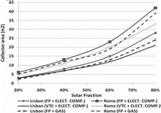
For the single-family house, in Rome it is possible to achieve economic viability for a solar system with gas or electric backup when the solar fraction is between 40-80% — see Figure 3. Comparing with a conventional electric air-conditioning, this system leads to a reduction of 3.8 c€/kWh of produced energy. In situations where an electric backup is not possible (only gas backup), solar systems installed in Rome and Lisbon with solar fractions between 20-80% are economically interesting. For Berlin, profitability occurs just with the use of a flat-plate collector and solar fractions between 20-40%. A gas boiler as backup solution, instead of an electric compression chiller, allows a reduction in solar collector area between 0-20% for the same solar fraction. In the Mediterranean cities, the flat-plate collector compared to the vacuum tube collector, allows a reduction in the total cost of produced energy between 0-2.2 c€/kWh — see Figure 3. In Berlin, for an electric backup both collector technologies show similar results, but for gas backup the flat — plate collector presents better results. Vacuum tube technology has the advantage of allowing a reduction of collector area between 5-45% — see Figure 4.
 |
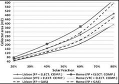 |
Fig. 3. Evolution of the total energy cost with solar fraction for electric (left) and gas (right) backup solution.
Fig. 4. Collector area needed according to annual solar fraction for the different building types.
By using an integrated solar system for combined heating and cooling, it is possible to save in total costs and CO2 emissions. This is particularly true for South-European locations, and economical results are more interesting when natural gas is used as system backup energy. Minimum costs depend on building type and location, but usually happen with annual solar fractions between 20 and 60%.
The single-family house and the hotel are the cases where the solar integrated system has a higher economic feasibility. Considering the present energy costs, Rome is the only city where it is possible to achieve a break-even situation. Compared to flat-plate collectors, vacuum tube collectors allow a reduction in collector area between 15 and 50%, although, due to their initial cost, flat-plate collectors lead to a higher economic viability. The best system in combination with solar is the electrical chiller; nevertheless, it is a gas boiler backup that leads to the best solar system efficiency.
An annual solar fraction of 60% can only represent a reduction between 35 and 45% of exploitation costs, because of significant maintenance and water consumption costs.
Although the exploitation cost of a solar assisted air-conditioning system is considerably lower when compared to a conventional system, the total cost (including investment, operation and maintenance costs) is actually high, even when extending the operation period as much as possible throughout the year. For solar cooling (and heating) to become more competitive, it is necessary that initial costs for absorption chillers and solar collectors are further reduced, considering the present costs of energy sources (gas, electricity).
[1] ESTIF, Solar Assisted Cooling — State of the Art. Report of project “Key Issues for Renewable Heat in Europe (K4RES-H)”, 2006.
[2] Solar Energy Laboratory, TRNSYS 16: A Transient System Simulation Program — Program Manual. University of Wisconsin-Madison, USA, 2004.
[4] IEA-SHC, TASK 38 — IEA Solar Heating and Cooling, 2007
[5] European Comission, Solar Air Conditioning in Europe, SACE, NNE5/2001/25, Evaluation Report, 2003
[6] European Comission, Solar Air Conditioning in Europe, SACE, NNE5/2001/25, Guidelines, 2003
[7] Henning H. S., Wiemken E., Solar Air Conditioning in Europe, SACE, NNE5/2001/25, Economic Study Report, 2003
[8] Henning H. S., Solar-assisted air-conditioning in buildings — a handbook for planners, second edition, Springer, 2007
Three absorption facilities are planned during this program to study small (less than 10kW) and large (more than 30kW) installations:
• Small installations will be tested on the LATEP and the SOLERA facilities.
• Large installation will be studied thanks to the RAFSOL installation worked out by the LPBS.
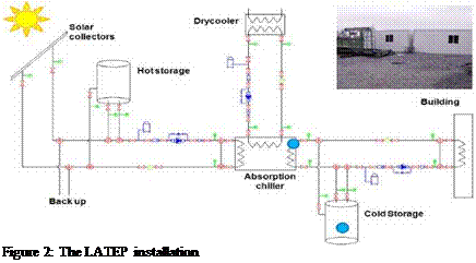 |
The LATEP project installation is a 4.5 kW Rotartica machine with a drycooler, a cold and a hot storage as shown on the following layout.
The SOLERA project is a European project started in November 2007, for 4 years. The sub-group 2 “small scale solar air conditioning in southern France”, is composed of French companies. The demonstration installation will be built in the new building of CEA-INES at Chambery, France. The chiller will be the one produced by Rotartica, with a nominal cooling capacity of 4.5 kW. The solar collector will be flat plate collectors and the terminal units will be high energy efficiency console units. The re-cooling system will be a geothermal heat exchanger able to dissipate 15 kW for a inlet temperature of 25 °C. The flat plate collectors will be located on the roof of the Puma III building (Figure ) and the system will be use to cool a modular area of offices located at the first floor
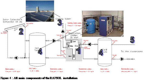 |
The main interest of the RAFSOL project is to propose a specific study of the absorption solar cooling processes in tropical climate. Moreover, this facility, designed to cool four classrooms of a university building operates without any backup system. The main components of the installation are proposed on the following figure:
1: absorption chiller (cooling capacity = 30 kW), 2: 36 solar collectors (total area = 90m2),
3: cooling tower (cooling capacity = 80 kW),
4: hot (V=1500L) and cold (V=1000L) storage, 5: cooling coils providing cooling in classrooms.
To model the absorption chiller we are going to use the operation curves of the chiller given by the manufacturer. Thanks to these curves and depending on the inlet temperature of the generator, we will be able to determine the frigorific power of the chiller, a generator power and cooling power.
3.3. The cooling tower
To model the cooling tower, we considered a heat exchanger. The first fluid (1: the water), circulates through the exchanger, while the second fluid (2: the air), blows around and against the first flow. We chose to use the efficiency method and the formula is [8]:
|
with, ДТ^-Tjl-Tzl, (m ■* Cp)mln = nrin(™a * C* ій£ * Cj, 1 — е[-в»а-ві |
|
1 — C * e1 |
|
(ill* Cp) |
|
<*,сии |
= T. ‘ ^ …… ‘ " ‘ ^ ‘ T;: — T;: = "T.. ‘ ‘ T.: — T.; [8]
3.4. The Building
Here we present a simplified model of our classrooms. To do this we will consider a single area building and its main features are:
|
Length = 13m |
Glass: Simple glazing (S = 25m2) |
Students = 105 |
|
Width = 13m |
Wall: reinforced concrete (thickness = 16 cm) |
Lighting: 22 neon lights of 58W |
|
Height = 3m |
Infiltration air flight= 1 vol/h |
Occupation : de 8h00 a 18h00 |
 [9]
[9]
[10]
We have now all equations needed to determine temperatures and powers throughout the day.
 |
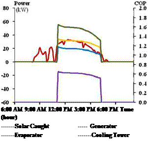 |
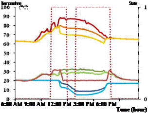
Our model needs to operate climatic data (sunshine and outside temperature). We chose those from the 2nd of June 2008. These data were derived from measurements made on our experimental platform by a weather station. Next, we must specify the time of occupation of the day: 10 AM to 12 PM and 1 PM to 5 PM. Then we have to set the initials temperatures inside the tow tanks (T_hot_tank = 66°C and T_cold_tank=20°C) as our installation on this day.
 Tout_captor
Tout_arai
T_cold_tauk —
Toutside —
occupation
Fig. 5 et 6: Evolution des temperatures et des puissances des principaux composants
We can see the evolutions of temperatures and powers on fig. 5 and 6. We notice that at 8 AM, the solar collectors start to produce hot water and the hot tank warms gradually. Students arrive at 10 AM (occupation = 1) and then leave at 12 PM. They come back at 1 PM and leave at 5 PM. The air temperature in the building increases with the arrival of students to reach its peak (30°C) 30 minutes later.
We see that the absorption chiller starts at 11 AM, and that the powers have been slowly declining throughout its operation (5 hours).
We can notice that the outlet temperature of the solar collectors does not exceed 90°C and the temperature of the hot tank reaches its peak at 11 AM and down gradually to 65°C at 4:15 PM, when the absorption chiller stops. Meanwhile the cold tank has reached its minimum value (about 8°C) at around 1 PM and the minimum outlet temperature of the evaporator is 6°C.
 |
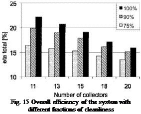 |
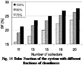
Due to the conditions on the site some degrading of the collector reflectivity could occur due to the effect of dust exhausted by a close chimney. This effect is presented in figure 14 and figure 15 for a system with varying number of collectors, a 2 m3 storage vessel and mass flow in the HX of 3000 kg/hr.
In systems with a small collector field the effect of dust has bigger influence on the solar fraction as well as on the overall efficiency. Because a bigger amount of heat is dumped due to overheating in systems with bigger collector fields only part of the radiation lost by the effect of dust is “missing” in the system, these losses reduce the total system efficiency with about 1% .While for systems with smaller solar fields, which dump less energy are therefore more affected by the effect of dust, and these losses reduce the total system efficiency with about 5% . With respect to this effect the collector field should be designed in an appropriate way to gain the expected heat and frequent cleaning measurements should be done for the collectors to ensure high fraction of cleanliness.
The preliminary development of a solar assisted refrigeration system has been object of a simulation study with the aim to characterise the main components. The innovative concept is meant for process cooling of received fresh milk in a dairy factory in the city of Marrakech, Morocco. A portion of the process has been selected and the daily cooling load profile has been characterized: cooling power and the duration of the cooling process. The system components’ selection and system configuration was carried out to ensure the highest solar energy use considering the given cooling load profile. Moreover a parametric study on the main system components has been worked out through simulations.
Regarding the collectors’ field area, its increase resulted in a growth of both, the solar fraction and the dumped energy. The latter is due to defocusing of the collectors when the input energy exceeds the demand; which can be significant for large collectors’ areas. As a result for the given application 18 modules of parabolic through collectors were selected, in order to guarantee enough thermal energy with an acceptable amount of dumped energy.
The optimum size of the PCM storage, for the selected collector area, is 2 m3. Considering the flow rate, a middle value of 3000 kg/h was selected as the flow rate for the cold side of the system, aiming at a compromise between increase in solar fraction and electricity costs. Three percent of the solar fraction depends on the cleanliness of the collector field, and this was taken into consideration during the sizing process as well as for the planned frequent maintenance of the system. As result of this study, the solar refrigeration system, which will be installed at the diary in Marrakech (October 2008) will consist of: 18 modules of parabolic through collectors, 2m3 PCM storage, with cold water flow rate of 3000 kg/h.
[1] H. Henning, A. Haberle, A. Lodi, M. Motta; Solar cooling and refrigeration with high temperature lifts — thermodynamic background and technical solution; — Proc. of 61st National ATI Congress, ATI-IIR International Session ‘Solar Heating and Cooling’,14th September 2006, Perugia, Italy
[2] M. Motta, M. Aprile, H. Henning — High efficient solar assisted sorption system for air-conditioning of buildings; — Proc. of Eight international symposium gleisdorf solar, 6th — 8th September 2006, Gleisdorf, Austria.
[3] Duffie, J. A., and W. A. Beckman; Solar Engineering of Thermal Processes; J. Wiley and Sons, 1991
[4] Tess Documentation Library, chapter 10.Solar Library Technical Reference, type 536: LINEAR PARABOLIC CONCENTRATING SOLAR COLLECTOR. pp536.1-5
[5] Solar Energy Laboratory, University of Wisconsin-Madison, USA et. al.; TRNSYS 16 — a Transient System Simulation program; http://sel. me. wisc. edu/trnsys/user-resources/index. html (08.08.2008)
[6] Eams, I. W. and Adref, K. T. (2002) Freezing and melting of water in spherical enclosures of the type used in thermal (ice) storage systems. Applied Thermal Engineering. 22, pp. 733-745.
[7] M. Aprile, Simplified models implementation, MEDiterranean food and agro Industry applications of Solar COoling technologies (MEDISCO). STREP — FP6 — EU contract Project no. 032559.
[8] Aprile, M. (2006) — Simulation study of an innovative solar absorption cooling system — Master Thesis “Dalarna University” 2006.