Как выбрать гостиницу для кошек
14 декабря, 2021
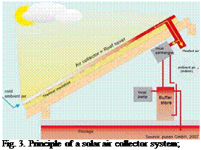
Air collectors can be found in systems for heating or pre-heating of the ventilated air in buildings (Fig. 3). All-polymeric solar air collectors or
 collectors with polymeric collector components are found in the market as small stand-alone units for dehumidification of week-end houses, cabins, garages, storerooms, etc. and for heating of large industrial buildings and residences. An example, which obviously includes the advantages of using polymers for solar collectors is shown in Fig. 3 and Fig. 8 (d): A modular roofing system of building integrated air collectors, which replaces conventional roof cladding and contributes to space heating.
In late 2007 a Fresnel process heat collector with 352 m2 aperture area (176 kWpth) was installed on the roof of the Escuela Superior de Ingenieros (ESI), a university building of the Faculty of Engineering in Seville, Spain. The collector has a total length of 64 m (16 modules, 4 m length each) and otherwise a similar design as the ones in Freiburg and Bergamo. The collector powers a double effect H2O/LiBr absorption chiller (Broad), with maximum cooling capacity of 174 kWth, for air-conditioning of the building. At this site the wet-cooling tower for heat rejection, which is usually necessary for H2O/LiBr absorption chillers, will be substituted by a water heat exchanger
fed by water out of the nearby river Guadalquivir. The double effect absorption chiller offers a high COP of up to 1.3, which makes this system a further attractive application of solar process heat for solar thermal cooling. First operation experience of the system is positive and measurement results are expected soon.
|
Figure 5. The PSE Fresnel collector in Seville, Spain, with an aperture area of 352 m2 (176 kWpth). |
The latest installation of our collector is at a winery in Tunisia, where the collector powers a 5TR NH3/H2O chiller from Robur. The installation was realized in the frame of a European funded project (MEDISCO), which will cover monitoring and performance evaluation of the system.
|
Figure 6. The PSE Fresnel collector in Tunisia (MEDISCO project) |
Both, the installation in Spain as well as the one in Tunisia are research / demonstration projects for solar cooling. However, from the viewpoint of the collector manufacturer both are commercial projects, which indicate the start of commercialization of the PSE linear Fresnel process heat collector.
As shown in Fig. 6, an angle plate, bended as a sector of a circle, is screwed at the front side of the collector prototype. Over this guidance a chain with a tensioning mechanism is led, which can be driven by a step motor over a gearwheel. The step motor is placed together with the control chip in a cabinet at the front side of the carrier. The control chip receives the sensors’ signal, which is placed on the top side of the collector. If the irradiation is not vertical to the aperture section, the control chip receives a differing voltage of the two photo cells insight the sensor which activates the tracking. The motor stops when the sensors’ signal is again equal zero.
|
Fig. 6. Tracking system with sensor, control chip and step motor |
The mentioned concept drives only one collector module, which was sufficient within the prototype stage. But since every trough needs its own actuation, the concept is not capable for an arrangement of a number of collectors in a field. In addition the actuation, especially the combination of chain, gearwheel and step motor, is not capable for a serial production, since the concept contains too many single parts. Furthermore the chain has a slip which makes the tracking rather insufficient if it is not clamped properly.
Planned optimization: As an optimized actuation, the new trough will be driven by a suspension link. These kinds of actuators, which are available as standardized components for tracking satellite antennas or big photovoltaic modules, have an adequate accuracy and enough power to drive several troughs. Each collector row is given an own suspension link and an own sensor. Thus, the rows operate autonomously and remain in operation, if one row is damaged or not in operation for attendance reason. A standardized component such as a PLC (programmable logical controller) will be used in the new concept.
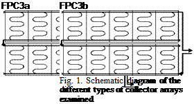
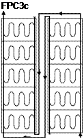
This model is based on a total of 210 outdoor stagnation experiments, which were carried out between 2003 and 2007 on three different collector types with a total of eight different connection variations (Fig. 1).
![]()
ETC1a/b
 |
 |
FPC2c
The SPP of a collector array depends on numerous parameters such as collector efficiency, system pressure and the piping of the collectors. During the stagnation process, we assume that the two — phase mixture in the collector array has the temperature of saturated steam $s. The theoretical collector performance during stagnation Pstag at the moment of maximum steam spread is calculated as follows:
![]() Pstag = GT, stag -Л0 “ a1 (S. )“ a2 (®. “ )2
Pstag = GT, stag -Л0 “ a1 (S. )“ a2 (®. “ )2
with
Pstag Theoretical collector performance during stagnation W/m2
GT, stag Effective irradiance during stagnation W/m2
Ss Boiling point of the heat transfer medium °C
Sa Ambient air temperature °C
p0 Conversion factor of the collector —
a1 Temperature-independent heat loss coefficient W/m2K
a2 Temperature-dependent heat loss coefficient W/m2K2
The boiling point 0S of the common heat transfer medium, which consists of a mixture of 60% water and 40% propylene glycol (40%), can be calculated with the help of the system pressure psys at the moment of maximum steam spread:
3S = 100°C + 35.1K • ln (pSyS) (2)
 |
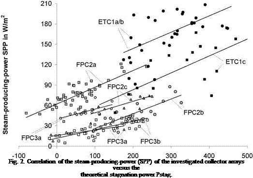
This calculation takes into account the influence of the system pressure psys, which has an impact on the stagnation behaviour through a changed boiling point. High-performance evacuated-tube collectors are more efficient during the stagnation process and therefore tend to a higher SPP. Hence, an interdependency of SPP and theoretical collector performance during stagnation Pstag is to be expected. Furthermore, the developed model, which describes the correlation of Pstag and SPP, is only influenced by the draining behaviour of the collector array. Fig. 2 shows the dependency of the measured SPP-levels on the theoretical collector performance during stagnation Pstag for the different collector types and array connections.
2
Theoretical stagnation power Pstag in W/m
Although there sometimes have been measured considerable differences in the SPP-values, Fig. 2 shows a clear trend. As expected, SPP rises with theoretical collector performance during stagnation Pstag. Furthermore, almost all lines of best fit have a positive axis intercept, i. e. a great amount of steam is produced by the collector arrays, although the theoretical collector performance during stagnation is zero. This is particularly clear to be seen with the measurement results from variant FK2a, where SPP levels of 60 W/m2 are recorded although the theoretical collector performance during stagnation is zero. The main reason for this discrepancy is the false model assumption, that the collector temperature during stagnation equals the boiling point 0S of the collector field. In fact, this assumption is often not valid for collectors with unfavourable draining
behaviour, because the relatively large amount of liquid remaining in the collector can significantly reduce the average collector temperature.
From the measurements at the outdoor test arrays at ISFH we can derive three classes of collector arrays with good (A), moderate (B) and bad draining behaviour (C). For these three classes the following correlations with rounded coefficients can be produced:
Class A: SPP = 15% Pstag + 10 W/m2
Class B: SPP = 20% Pstag + 40 W/m2 (3)
Class C: SPP = 25% Pstag + 80 W/m2
The designation of the collector draining behaviour during stagnation process is the basis for the following design process. If we calculate SPP using the model equations (3), a standard deviation between the measurement results and the prediction of 25% may be expected.
M. Hermann
Fraunhofer Institute for Solar Energy Systems, Heidenhofstr. 2, 79110 Freiburg, Germany
Tel.: +49 7 61 / 45 88 — 54 09, Fax: +49 7 61 / 45 88 — 94 09
michael. hermann@,ise. fraunhofer. de
Abstract
Aluminium becomes more and more interesting as a solar absorber material. One possibility to produce an absorber entirely made of aluminium is given by roll-bond technology which is well established for large-scale series production of e. g. evaporators for refrigerators. This technology offers the possibility to build solar absorbers with high efficiency, since the channel design can be varied without additional costs. At Fraunhofer ISE a computer algorithm called FracTherm® was developed which is capable of generating a fractal-like, multiply branched channel design on a given area (also non-rectangular), similar to natural hydraulic networks. The aim of this bionic approach was to obtain a high efficiency by means of a uniform flow distribution as well as a low pressure drop. A small solar collector with FracTherm® roll-bond absorber (0.59 m x 1.0 m) had already been built and compared with absorbers featuring serial (meander absorber) and parallel (harp absorber) channel arrangements, respectively, within the research work of a doctoral thesis. Since the test absorber was relatively small, the focus of current research and development is on investigations of larger absorbers with sizes typical for solar collectors. This work, which is still at the beginning, will be done together with industry partners within the European project BIONICOL. This paper describes the challenges coming up with the development of large aluminium roll-bond absorbers with FracTherm® channel design including issues such as inside and outside corrosion, application of a selective coating, the connection of several roll-bond absorbers, fluid flow investigations and stagnation behaviour.
Keywords: FracTherm®, roll-bond, bionic, aluminium absorber
State-of-the-art solar collectors with fin-and-tube absorbers mostly feature serial (serpentine or meander absorber) or parallel (harp absorber) channel arrangements. However, serial arrangements lead to a high pressure drop due to the channel length, whereas the parallel arrangements can feature non-uniform flow distributions (depending on diameters and lengths of riser and header tubes) [1]. The bionic so-called FracTherm® approach developed at Fraunhofer ISE (Fig. 1) allows creating fractallike, multiply branched channel structures on a given area which lead to a low pressure drop as well as a uniform flow distribution. The resulting complex structures are not suitable for being built as a fin- and-tube construction, but they can easily be realized as aluminium roll-bond absorbers. Small
FracTherm® test absorbers (0.59 m x 1.0 m) had already been designed, built and compared with meander and harp absorbers within the frame of a doctoral thesis. These investigations had already been published in detail in [2], [3] and [4]. The thermal efficiency had been very high for all test absorbers. It could have been shown that the flow distribution of the FracTherm® absorber was much more uniform and the pressure drop for high volume flows was up to 8 % less than in the roll-bond harp absorber. However, both the results of the experiments carried out so far and the construction of the collector are not directly scalable to a standard size collector (1.0 m x 2.0 m). Fig. 2 shows the small test absorber investigated earlier and a standard size collector with a possible FracTherm® channel structure. The questions arising with the development of a large aluminium absorber with FracTherm® channel design are to be answered within the European research project BIONICOL.
|
Fig. 1. The FracTherm® algorithm |
|
Fig. 2. Test absorber (left) and standard size absorber to be developed (right) |
Kerr MacGregor*
MacGregor Solar, 31 Temple Village, Edinburgh, Scotland EH23 4SQ
tel +1875 830 271
* Corresponding Author: kerr @macgregorsolar. com
Abstract
This paper describes a novel method of building large, cheap solar water heating collectors on site. It is based on using synthetic rubber pipes with enhanced thermal conductivity which are squeezed against the underside of an aluminium solar absorber sheet. The collector can easily be built on site using unskilled labour at a relatively low cost. In addition the collectors are freeze-tolerant and can handle corrosive fluids.
Several attempts have been made (Bartelsen et al, 1999) to use polymers pipes for solar heat collectors. However, these require specially formed absorber plates to encase the pipes. This method uses plain, flat absorber sheets which are cheaper and more readily available.
The starting point is a foundation board which can be of timber or chipboard. A layer of thin insulation e. g. reflective bubble polythene is then laid on the foundation board. A grid of the polymer pipes is then laid on the insulation, spaced at about 150mmcentres. The pipes can be temporarily held in place by adhesive tape. Then a sheet of highly conductive material, e. g. aluminium, is laid on top of the pipes and is fastened using screws to the underlying foundation board. The thickness of aluminium and pipe spacing are chosen so that the polymer pipes are squeezed against the underside of the aluminium, but are not closed to the passage of fluid. The aluminium sheet is then painted with a solar absorbing paint. Alternatively, aluminium which has a selective surface can be used. Finally, glazing such as twin wall polycarbonate is located over the absorber and held by glazing bars. A diagram showing a cross-section of the collector is shown in Fig 1 below.
|
Fig 1: A cross-section of the absorber 3. Suitable piping material |
Obviously the pipe material should have good thermal conductivity and long life. EPDM has been previously used. Its thermal conductivity can be enhanced by including materials such as carbon black or graphite in its composition. That can also increase the mechanical strength of the polymer. For example, the addition of 40phr of carbon black to EPDM can increase thermal conductivity from 0.2 to 0.5 W/mK and tensile strength from 3Mpa to 17Mpa. It should also increase resistance to UV degradation, though in this application the tubing is shielded from solar radiation.