Как выбрать гостиницу для кошек
14 декабря, 2021
1.4. South-Facing Curtainwall Facade Scenarios
The impact of the five different south-facing curtainwall facade scenarios described in Table 2 on a building heating and cooling load was studied for the three cities identified in Table 1. For each scenario, the curtainwall was assumed to consist of 50% of a multi-layer glazing system as a vision section, and 50% of either spandrel panels or multi-glazing BIPV assemblies as the non-vision section. All the multi-layer glazing systems (with and without PV) were assumed to have low-e coating, 6mm glass panes, 20mm air cavities and aluminium framing with 19mm thermal break and insulating edge spacers. The vision sections characteristics were obtained with FRAMETMplus [13] using the curtainwall framing system. The U-value and SHGC were evaluated at 2.03W/m2oC and 0.39 for the double-glazed system, and 1.2 W/m2oC and 0.28 for the triple-glazed system.
|
Table 2. South-facing curtainwall facade scenarios.
|
The classification of fa? ade systems by “morphological” aspects, i. e. form, dimension, construction, material, function etc. led to a great variety, (23 parameters and up to six variations per parameter in the morphological box). The number of classified solutions could dramatically be reduced, if only the physical properties were considered, which had an influence on the energy demand. It was possible to reduce the 23 parameters to six energy relevant parameters: window/fa? ade (Awindow), mean heat transmittance of fa? ade (Um), heat gain coefficient of glass (gG), heat gain coefficient of shading devices (FC), light transmittance of glass (TL), equivalent air change rate (neq). For each parameter there are defined five equidistant values, the bandwidth between lowest and highest value given by minimal building standards and best practice solutions (Table 1).
Table 1. Equidistant steps and bandwiths of relevant parameters (U-values of opaque and transparent elements
were combined to a mean faqade value)
|
north |
East |
south |
west |
— |
|
0,300 |
0,475 |
0,650 |
0,825 |
1,000 |
|
0,150 |
0,290 |
0,440 |
0,580 |
0,720 |
|
0,500 |
1,080 |
1,650 |
2,230 |
2,800 |
|
0,370 |
0,460 |
0,560 |
0,650 |
0,740 |
|
1,0000 |
0,8125 |
0,6250 |
0,4375 |
0,2500 |
|
0,510 |
0,585 |
0,660 |
0,735 |
0,810 |
|
0,180 |
1,010 |
1,840 |
2,670 |
3,500 |
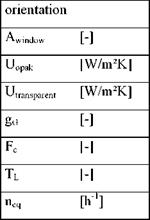 |
In total there were 15,625 facade combinations to be simulated by TRNSYS for each of the (four) major fa? ade orientations. All simulations were carried out under the same boundary conditions, such as office floor plan and weather data.
Villa Zagala is located at 34.6° South, 58.5° West, and 26 m over sea level, in “Great Buenos Aires”. There are neighbouring buildings, such as a hospital and a geriatric house and a church that conditionates the orientation of the new building. The climate variables in winter and summer are shown in Table 1. The outdoor air temperatures and wind velocities were obtained from the National Meteorological Service and the mean solar irradiance on horizontal surface was estimated from correlations (Righini et al., 2004).
|
Table 1. Meteorological data of Villa Zagala, for a winter (July) a summer (January) month.
|
The floor view and two facades are shown in Figures 1 and 2. The original project was a conventional design commonly used by the Ministry of Social Development (MDS) team in these buildings with slight adaptations depending on the site. Due to functional reasons, the CIC building is divided in two independent sectors, named Health and Development, with a covered area around 325 m2 each one. The Health Sector has a large vertical surface oriented to North in order to maximize the solar collection. Originally the vertical envelope was a plastered hollow ceramic wall (0.18m thick), with indoor partitions of 0.15m thick hollow ceramic bricks. The roof was a metal sheet with a gypsum ceiling. This project was modified in order to minimize the thermal losses through the building envelope by improving the thermal insulation of walls and roofs with a polystyrene sheet (0.05m thick), the subfloor with insulating aggregates and double glazing in windows. Reduction of the air leakages through the opening frames, avoiding overheating in summer through solar control devices as overhangs, shading devices, etc., forced and natural ventilation, and daylighting, were also included. Solar and low-energy devices as solar water heating, photovoltaic panels, and low-energy consumption lights, will be installed in the building.
In this project a design concept for PV powered PDA (Personal Digital Assistant) was designed. The design was made with the aim to use the matching model. The main challenge of the project
was to integrate a PV surface larger than the functional product in such a way that it can optimally convert energy and users can conveniently use the product. The final product design is a mobile device that is highly energy efficient. The target group consists of users that have a modest demand for functionality and thus energy consumption. The PV panel is foldable and detachable. Folded, the panel is small enough to fit in the cover of the device. When detached the panel can be left to charge its own battery on a location with high light intensity. The main device can be used on a different, darker, location. As soon as the panel is connected to the device again, the energy stored in the panel’s battery is transferred to the device’s battery.
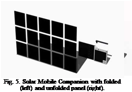 |
A tangible model was made of the product. The final design is a concept, a showcase. It is estimated that the design is technically feasible in terms of technology by the year 2010.
The first and often most difficult stage of planning a solar cooling plant is to calculate the actual cooling demand. Norm calculations usually give the sum of multiple single peak loads resulting in a very high overall peak load. This demand however will only be required for a very small number of running hours. This explains why electrical cooling machines are mostly over-sized and therefore have to continuously modulate. This unstable operation leads to lower efficiency levels and unnecessarily high power connections.
If a solar thermal cooling plant was to be designed based on these peak loads, the plant would not only be very expensive, the over-sizing also leads to operational problems.
|
Table 1: Overview of the thermal cooling plants already operational from S. O.L. I.D.
|
All of the cooling projects for air-conditioning purposes were over-dimensioned by a factor of 2-3 during the initial design phase. According to the DIN, the EAR Tower in Pristina had a cooling demand of 210 KW. The actual cooling system installed by S. O.L. I.D. uses two cooling machines with a total nominal capacity of 70 KW (peak 90 KW) and a back-up 30 KW compression cooler. The maximum measured cooling demand over six summers (including the particularly hot summer of 2003) was 80 KW. Same has been monitored on all other projects.
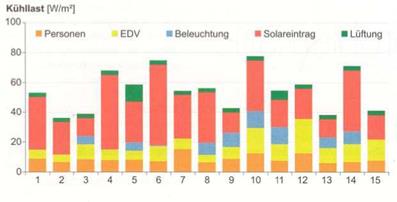
The influence factors on the cooling demand are as well as people, IT equipment, lighting and ventilation, most notably passive solar gains.
A realistic estimate of the cooling demand requires further experience or a simulation programme.
The cooling demand also varies considerably depending on ventilation, in particular rates of air change and heat recovery installations play a big role.
For air conditioning in office buildings, a ratio of 12m2 collector area per 100m2 of office area to be cooled has proven to be relatively accurate. Larger collector areas are necessary only in extreme climates with high cooling demands at night.
Diagram 1: shows measurements from a typical conventional cooling machine in the USA. Notable is that during over 90% of the running hours, the cooling demand was lower than 20% of the installed capacity,
 |
and 99% of the time lower than 30%.
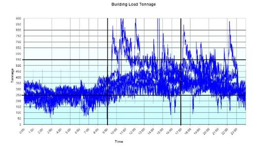
Diagram 2: This building has a nominal load of 1200 tons, however, even in peak seaseon operation is
 |
mostly between 250 and 500 tons.
Diagram 3 Cooling demand in different Austrian buildings (Source: Fink et al, AEE Intec)
Due to the high electrical coefficient of performance of conventional compression chillers, the primary energy consumption is despite the use of electricity still reasonable. In order to save primary energy with replacing these systems with a solar thermal driven air conditioning system and a thermal back-up system using fossil fuels, high solar fractions and high coefficients of performance of the cold production are necessary. The coefficient of performance depends mainly on the chiller technology and on the temperatures in the heating, cooling and re-cooling circuits.
For temperatures delivered by typical solar collectors and for typical absorption chillers, this value does not vary much and is in the range of 0.6-0.8. Based on such a thermal coefficient of performance and compared to typical compression chillers with electrical coefficients of performance of about 3.5, only solar air conditioning systems with solar fractions of more than 60% are leading to primary energy savings [2].
However, the solar fraction of a solar air conditioning system depends on many factors of which the most important are:
■ Time dependent matching of available heat from the solar thermal system and cooling demand
■ size of the solar collector field
■ efficiency of all system components
■ storage capacity
■ control strategy
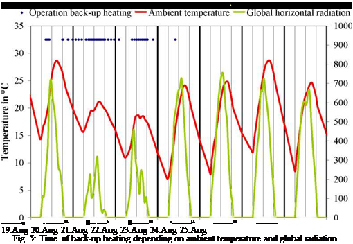
For the reference case in the simulation studies, a flat plate collector field with an area of 150 m2, which would be appropriate for typical solar air conditioning applications using absorption chillers with a cooling capacity of 50 kW, and a hot water store volume of about 16 m3 was chosen. With this configuration, a significant contribution of the solar thermal system to the cold production was determined. However, the solar fraction for cooling of the office rooms, seminar rooms and the server room determined for the the building described was less than 50 %. Regarding this, Fig. 5 shows the back-up heater operation depending on ambient temperature and actual irradiation for a period in August. It can be seen that back-up heating is mainly required during times of high ambient temperatures but comparable low irradiance.
 |
Thus, it can be expected that a change in the system configuration of the solar thermal system can increase the solar fraction. Regarding this, three different approaches have been investigated:
a) Collector area:
Increasing the collector has a significant effect on the solar fraction. It could be shown that doubling the collector area can increase the solar fraction up to 70 %
b) Collector type:
Changing the collector type to 150 m2 vacuum tube collectors can increase the solar fraction up to 75 %
c) Storage volume:
Doubling the storage tank volume can increase the solar fraction only up to around 65 %
Based on these investigations, it could be shown that with an adjusted system design, high solar fractions for cooling are possible. However, all these adjustments are leading to high investments. Due to this, alternative concepts need to be investigated. Some of these are discussed as follows:
Alternative storage concepts
Because of the small temperature step of supply and return flows during the operating of absorption chillers, the effective storage capacity of water tanks is limited, especially since temperatures of more than 80°C are required to drive the chillers. Thus, due to a high storage density at small temperature steps, a replacement of water storage tanks by storage tanks using phase change materials seems to be promising. Herewith, a reduction of the storage volume of down to 1/5 seems possible.
Alternative cooling technologies
Since mostly summer days with low radiation are responsible for the relatively low solar fraction, alternative solar cooling technologies which require lower driving temperatures could overcome
this problem. Since server rooms are usually cooled with ventilated air, open cycle systems using liquid dessicants, e. g. [7], can lead to efficient system designs. These systems require temperatures of only 60-70°C, which can be supplied even on days with lower radiation.
Different server room temperatures
One approach to further decrease the energy demand for cooling of server rooms is the increase of the room temperature in the server room itself. Investigations in [8] on the tolerable temperature of data processing equipment are recommending temperatures of up to 26°C. With such an increase, the proportion of free cooling would be, especially for Germany, increased by a large extend. However, the solar fraction of the remaining cooling demand would not necessarily increase, too.
Integrated system for heating and cooling
To increase the overall efficiency of the system for heating and cooling, the use of waste heat from the server room for heating the building in winter times should be applied. For this, the amount of energy reduction depends on the efficiency of the ventilation strategy and its heat recovery system as well as on the temperature in the server room. In addition, heating can be supplied by the solar thermal system at times when the energy is not used for the cooling process. In that case, the yearly gain of the collector field would be increased. However, the amount of primary energy reduction depends on the building design, too.
Bivalent cooling strategy
If the solar fraction cannot be increased with one of the measures mentioned above, a bivalent cooling strategy would still lead to significant primary energy reductions. In that case, both thermal driven chillers and vapour compression chillers would be used for the cooling of the building and the server room. As long as thermal energy would be available from the solar thermal system, the thermal chiller would supply the cold. As back-up during times of low radiation, the conventional electrical chiller would be operated. A draw-back of this approach is that the investment would increase due to the requirement of two different cooling technologies. Furthermore, the complexity of the design and operation of the system itself would increase, too. However, both issues would be eliminated if an emergency back-up system would be required anyway and if such a system could be used as a normal operational back-up, too.
3. Conclusion
In the present paper, investigations on using solar thermal energy to cool a passive office building with seminar rooms, office rooms and especially a server room are presented. It could be shown that even if the cooling demand for the seminar and office rooms of the investigated building is quite small, the peak cooling load can be significant even if appropriate shading devices are used. Due to the good coincidence of solar radiation and cooling demand, solar air conditioning systems can lead to significant improvements of the user comfort. Due to the relatively constant cooling demand of a server room, special measures have to be implemented in order to use the solar thermal systems to cool the server room, too. It was shown that the use of ambient air during cold or mild periods can reduce the cooling demand of the server room by almost a factor of 3. Thus, ambient cold represents the most efficient way to reduce the energy demand for cooling of server rooms. In addition, it was shown that with this reduced cooling demand, which almost matches the solar radiation available, the use of solar air conditioning system can reduce the primary energy demand for cooling even more. However, for a significant primary energy reduction compared to the use of conventional compression chillers, high solar fractions are necessary. Thus, for a special
application, it needs to be proven whether additional measures like the use of compression chillers as back-up, or the use of the solar thermal system and the server waste heat for heating the building during winter time, can be applied.
5. Acknowledgment
The authors wish to thank the company Wagner& Co Solartechnik for supporting the investigations presented in this paper.
References
[1] European Commission, (2007). Green Paper — Adapting to climate change in Europe — options for EU action, Brussels
[2] Henning H.-M., (2004). Solar-Assisted Air-Conditioning in Building — A Handbook for Planners. Springer-Verlag Wien
[3] Mines Paris ParisTech — Center for Energy and Processes, (2008). High efficiency and low environmental impact air-conditioning systems Air-conditioning key figures in the world, in Europe and in France, http://www. cenerg. ensmp. fr/english/themes/syst/index. html.
[4] EnergieAgentur. NRW (2008). Ohne Energie keine Information — Rationelle Energieverwendung in Rechenzentren und EDV-Raumen. Wuppertal.
[5] Afonso, C. F.A. (2006). Recent advances in building air conditioning systems, Applied Thermal Engineering, Vol 26.
[6] H.-M. Hellmann, C. Schweigler, F. Ziegler, (1999). The characteristic equation of sorption chillers. Proc. Int. Sorption Heat Pump Conf., Munich, 24.-26. March 1999; pp. 169-172.
[7] Lavemann, E., Peltzer, M. (2003): Solar Liquid Desiccant cooling System Demonstration Plant, ISES Solar World Congress, Goeteborg, 14.-19.6.2003.
[8] American Society of Heating, Refrigeration and Air-Conditioning Engineers (ASHRAE) (2003). Thermal Guidelines for Data Center and Other Data Processing Environments. Atlanta, U. S..
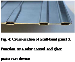
First of all, the collector can be regarded as a fa? ade collector with its typical advantages, disadvantages and special aspects to be considered in order to be designed properly. One of these important aspects is the minimum backside insulation [3, 4] to prevent the room from overheating. In the case of the semi-transparent collector these minimum insulation requirements have to be fulfilled by the inner glass pane(s). Depending on the efficiency of the collector and thus its temperature level, it will be necessary to use a double glazing with Low-E coating as “backside insulation” or multilayers of transparent foils [7]. Another important topic will be the effect of the openings and the position of the absorber on the natural convection within the collector and thus on its efficiency. In order to have a high flexibility concerning the absorber channel design as well as an aesthetic appearance, roll-bond absorbers (Fig. 4) seem to be a good choice for this type of collector. In conventional absorbers, the heat transfer direction from the absorber surface to the next channel is basically perpendicular to the channel direction. In the case of an absorber with a three-dimensional structure it has to be considered that the heat transfer distance to the fluid is increased and the cross section is reduced: The sides of the lamellae (bent to outside) are not in contact with the channel; therefore the heat transfer is only possible via the remaining flat areas of the absorber which are connected to the channels. The advantage of roll-bond absorbers is the fact that their channel distance can be reduced without additional costs. It can be expected that smaller channel distances will compensate for the lower heat transfer of the three-dimensional structure mentioned above and thus lead to high collector efficiency factors F’ anyway. Moreover, for large sun elevation angles the incidence angle modifier (IAM) of the lamellae should be higher than for a flat vertical absorber. This could be beneficial for solar gains in summer in order to drive a solar cooling system. Roll-bond technology also offers the possibility to realize optimized channel arrangements such as fractal-like, multiply branched FracTherm® structures which lead to a low pressure drop as well as a uniform flow distribution [5, 6]. Even non-rectangular shapes can be used, which might be interesting for architectural reasons.
Regarded as a window-like building component, the three-dimensional structure of the absorber leads to an angular-selective behaviour. Depending on the geometry of the openings and their coating the properties concerning absorption, transparency, daylighting, solar control and glare protection can be adjusted according to the specifications of the particular application. Fig. 5 shows some principal variations of geometry and coating. Variant a) mainly focuses on absorption, transparency, solar control and glare protection, but it will have a poor performance with respect to daylighting since there are no reflecting surfaces leading the sunlight to the inside. In contrast to a), the diffuse reflector of
 |
Variant b) features better daylighting behaviour, but poor absorption, solar control and glare protection. Variants c) and d) can be regarded as compromises of a) and b) with different focuses.
 |

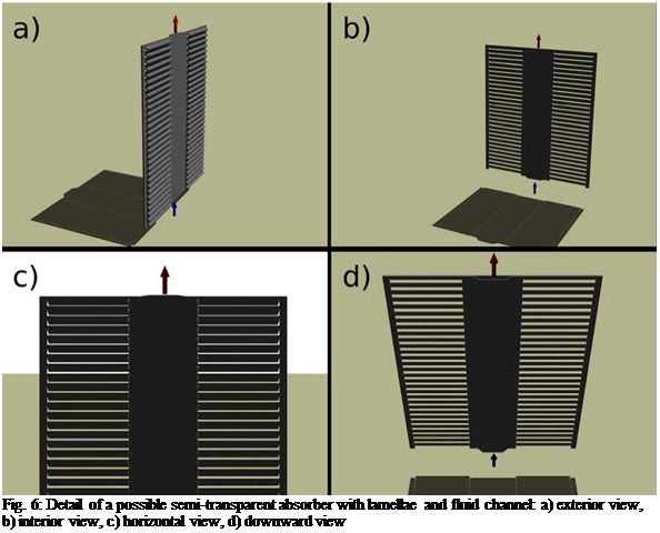
In Fig. 6 different views of a detail of a possible semi-transparent absorber with lamellae and fluid channel are shown. The size of this small part is only about 128 mm x 150 mm. The exterior view in a) gives an impression of the absorber seen from outside, whereas the internal view in b) shows the appearance from inside. It can be seen that for the assumed sun elevation angle a homogeneous shadow is formed (without light stripes from the openings). View c) and d) show how the effective transparency changes with the angle: only small slits appear if one looks through the absorber horizontally, but they seem to become bigger if one looks downwards. This effect is especially interesting for multi-storey buildings.
Fig. 7 shows the absorber detail at different incidence angles of the sun. In the raytracing simulations the absorber was oriented towards south and the solar azimuth angle was always 0. It can be seen that even for small incidence angles the shadow is homogeneous.
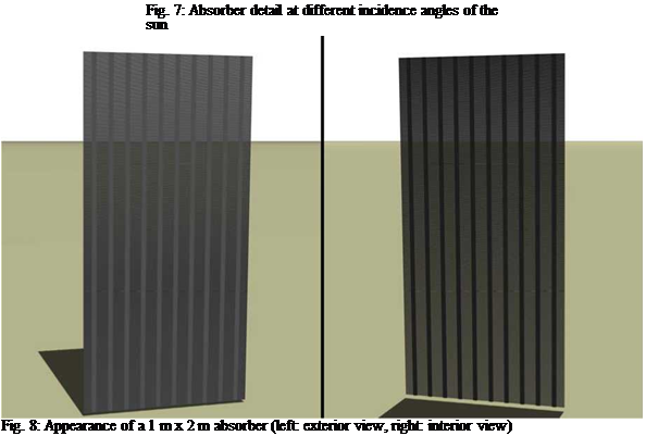
Fig. 8 gives an impression of the appearance of an absorber with an area of 1 m x 2 m and its shadow. In this case parallel, vertically oriented channels were assumed. However, other channel designs are also possible.
The typical room used for the studies is a standard cross ventilated classroom, 7 x 7 x 2.7 m. The external concrete wall are 16cm thick with three windows for each facades (see Figure 3). Different values of porosity (percentage of openings with regard to the facade) to quantify the
impact on the autonomy in natural lighting. Two azimuths have been considered for the main facades : North and South then East and West
Only a overhang solar shading type has been considered. The TMY weather file used is the one from Saint Pierre, a town located in the south of La Reunion.
The classroom has been divided into three equal strips. The daylight factor and the illuminance level have been calculated for each strip.
|
|
The differences between the values of HDD and CDD obtained from the different of measurement sites (urban and rural stations within MMA and the local weather station at the airport) were calculated. These differences were expressed as percentages in order to quantify the error’s magnitude incurred in the calculation of the studied variables when not considering the effect of the city on the local climate.
|
Table 3. Monthly values of HDD y CDD corresponding to the north transect. Stations 50 vs. 59 and the Airport’s station are compared. (See figure 1)
|
|
Table 4. Monthly values of HDD y CDD corresponding to the south transect. Stations 50 vs. 40 and the Airport’s station are compared. (See figure 1)
|
|
Table 5. Monthly values of HDD y CDD corresponding to the west transect. Stations 50 vs. 3 and the Airport’s station are compared. (See figure 1)
|
|
1st International Congress on Heating, Cooling, and Buildings, 7th to 10th October, Lisbon — Portugal /
|
|
Table 6. Monthly values of HDD y CDD corresponding to the east transect. Stations 50 vs. 15 and the Airport’s station are compared. (See figure 1)
|
The results show that during summer time there exists an underestimation in the cooling demand calculated from the data obtained by local weather stations that oscillates between 6% and 43%. For the winter time, it happens oppositely, an overestimation of the heating load that represents an error from about 19% to 50%.
In the case of the air temperature behavior in downtown respect to its surroundings, it is observed that the demand for cooling in the downtown area is higher than 12% and up to a 130% respect to the surroundings demands, depending on the month of a year and the zone of the city analyzed.
The demand of heating for downtown area respect to the environs is smaller in the order of 25 to 62%.The energy requirements of the suburban and rural zones of the city respect to the values calculated from the local weather station show an overestimation of 4% to 41% of the cooling necessities, and an underestimation of 2% to 32% in the case of the heating demand.
Figure 3 shows the yearly distribution of HDD and CDD within the AMM. The degree day’s distribution responds clearly to the thermal behavior and to the climatic conditions that prevail in the city. During the summer the radiation levels are high, for this reason the materials that compose the ground of the city’s out-skirts, which are mainly rocky, accumulate heat during the day, homogenizing the distribution of temperatures between downtown area and the city’s out-skirts of the. This does not happen in winter due to the lesser amount of radiation during the day, increasing the temperature differences between downtown and the rural areas.
The greater demand in refrigeration during the month of December can be explained by the increase of the anthropogenic contribution in the city, because this is a festive month, whereas January and February are months of vacations. The maps that show the distribution of heating and cooling degrees-day within the AMM always display a hot zone of greater demand of refrigeration and minor demand of heating coincident with the administrative-commercial zone in the city.
The financial analysis combines the impact of different system implementation costs (400€/m2 and 600€/m2) and sale prices of PV electricity to the grid, in a total of eight scenarios:
• 0.08€/kWh: the typical average cost of electricity bought to the grid
• 0.20€/kWh: an estimate of the corrected value of electricity bought to the grid, taking in account the rise of the oil barrel prices in the last years
• 0.40€/kWh: the typical value of renewable PV generated electricity sold to the grid in Portugal
If all PV produced electricity is sold to the grid, the simple payback periods of the PV systems are:
Figure 7 — Payback of the PV system if all electricity produced by the schools is sold to the grid
|
|
Alternatively part of the PV generated electricity may be used in the school, leading to different payback periods. Considering that all the electricity produced during the week days will be consumed in the school (a saving of 0.08 €/kWh on the electricity bill of the schools, 45% of the days in a year), and that for the reminder of the days, including weekends and holidays (55% days of the year) the electricity produced is sold to the grid at the three prices previous addressed, a new payback periods is obtained (see figure 8).
|
Figure 8- Payback of the PV system if part of the electricity produced, 45% days of the year, is used in the school (the rest will be sold).
|
3. Conclusion
This study determined the following average values for the implementation of PV system in Portuguese high schools:
Table 2 — Summary table for this study
|
School Type |
РУ Area m2 |
PV Capacity kW |
Cost k€ |
Cost Є/m2 of floor area |
Electrical demand reduction % |
Energy Class |
|
P |
1000 |
140 |
500 |
62 |
50 |
A, A+ |
|
NP |
480 |
60 |
240 |
26 |
20 |
B, A |
The total PV potential of the 172 schools is approximately 144 000m2 with a capacity of generation of 25GWh/year.
The implementation of this systems is more favorable for pavilion schools due to their higher PV to floor area ratio and easier installation and maintenance of panels (flat accessible roofs).
The electrical energy autonomy values obtained, based on the energy consumption for a typical school do not consider the effect of additional optimization measures (lighting, natural ventilation etc.). It can be expected that, for the best cases, after those optimization measures, to achieve values of autonomy close to 100% (on a net yearly base).
If the electricity produced is sold to the grid at a realistic price, unsubsidized price of 0.20€/kWh, the simple payback varies between 11 and 17 years, for both scenarios considered. The payback varies notably with the cost of PV per square meter and with the PV electricity sale price to grid.
|
References |
[1] Study for Parque Escolar: Avaliagao do Potencial Solar Fotovoltaico, NaturalWorks,
2008.
[2] Decreto-Lei 80/2006, de 4 de Abril, Regulamento das Caracteristicas de Comportamento Termico dos Edificios (RCCTE)
[3] Decreto-Lei79/2006, Regulamento dos Sistemas Energeticos de Climatizaqao em Edificios (RSECE)
[4] Decreto-lei n° 78/2006 de 4 de Abril aprova o Sistema Nacional de Certificaqao Energetica e da Qualidade do Ar Interior nos Edificios (SCE)
[5] European Union directive 2002/91/CE
[6] Solterm Software, INETI, Portugal
[7] Portuguese Energy Agency (ADENE): http://www. adene. pt/
[8] International Energy Agency, Portugal, Energy Balance, 2005.