Как выбрать гостиницу для кошек
14 декабря, 2021
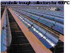
Figure 1 summarises the situation until recently in a simplified way: There existed well developed collector technologies (flat-plate and vacuum tube collectors) for systems that operate at collector temperatures up to 80°C. And since many years large parabolic trough collectors operating at about 400°C are available. But what is an appropriate collector technology in the temperature range between these two established technologies? The development of suitable process heat collectors in this temperature range (sometimes called ‘medium temperature collectors’ for this reason) is important for new developments and further diversification of applications of the solar thermal technology. The practical experience up to now is only limited to and concerns mainly the lower temperature range of up to 80°C. Solar systems which deliver heat for washing and cleaning processes in the food and beverage industry may be mentioned, see [2]. Important and very interesting fields for collector applications at higher operating temperatures are solar air conditioning and cooling [3], solar sea water desalination [4] and water purification, besides industrial process heat.
It has to be mentioned here that well developed evacuated tubular collectors exist which can be regarded as process heat collectors for applications up to about 160°C with respect to their thermal performance. But also those are not often used up to now for the application in process heat systems.
 |
 |
Partly this is due to the fact that other additional conditions which are often or generally met in industrial processes are of concern, such as the large size of the systems, costs, stagnation times and
low medium high
temperature temperature temperature
range range range
Figure 1: What is the appropriate collector technology for the medium temperature range from 80°C to 250°C? Experience from concentrating and non-concentrating collector technology will merge in the development of new process heat collectors for operating system temperatures above 80°C.
stagnation behaviour of large collector fields, appropriate solar loop fluid with sufficient temperature resistance etc. The temperature limit for water-glycol mixtures as solar fluid lies in the range of 150°C. With respect to this topic, some system providers work with water in the solar loop. But then other solutions for freeze protection are required. Not only, but also with respect to these solar fluid related difficulties Fraunhofer ISE has started to work again on solar air collectors [5].
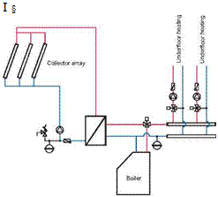
In most solar space heating systems applied in factory buildings, standard system concepts have been used — collectors heat a storage tank that feeds into an underfloor heating system (see Figure
3).
 |
 |
 |
 |
Another option would be to use the thermal mass of the concrete floor of the building, which has a large storage capacity, to replace the storage tank entirely (see Figure 4). This is possible because most industrial buildings have a relatively thick concrete floor and the required room temperatures are typically lower than in residential buildings.
Figure 3. System concept with storage tank. Figure 4. Hydraulic layout without storage tank,
the concrete slab is used to store solar heat.
An additional step to simplify the system would be to abandon the heat exchanger and to fill the entire system with antifreeze fluid. The disadvantage of this concept is that a large quantity of antifreeze fluid is needed depending on the size of the building. The anti-freeze fluid is expensive and has to be replaced from time to time. On the other hand, the cost of the heat exchanger can be saved and there is no loss in temperature from the collector to the space-heating loop due to the heat exchanger.
If the concrete floor is used to store heat, it should be charged whenever there is heat available from the collectors even if the room temperature is already reached. This way, the storage capacity of the floor can be best used. Of course, both room temperature and floor temperature should not pass certain specified limits. The European standard EN 1264 states maximum floor surface temperatures of 29°C in the central part of the floor surface and 35°C in the peripheral zone. These temperatures are determined by physiological considerations.
The dimensioning guidelines presented are based on simulations [1] of the reference buildings with different heating system concepts and system sizes (collector areas 100 — 400 m2). Weather data for Graz, Austria and a standard flat plate collector [po=0.8, c1=3.5 W/(m2K), c2=0.015 W/(m2 K)] were used. To avoid detailed simulation calculations in the pre-planning phase, generally applicable dimensioning nomograms were developed to allow a rapid and reliable estimate of the collector area and the solar storage tank volume for space heating applications in factory buildings.
Apart from the key data for the solar thermal system, the solar fraction to be expected for the project in question and the specific solar yield can be read off the nomogram. The solar fraction is defined as
![]()
![]() Solar Fraction = 1 —
Solar Fraction = 1 —
Qconv
where Qaux Energy delivered by the auxiliary heating system, kWh/a
Qconv Energy needed for space heating without the solar thermal system, kWh/a
To simplify the use of nomograms, the "utilization ratio" is defined as an important auxiliary characteristic number. This is a measure for the dimensioning of solar thermal systems and describes the ratio of annual consumption to the collector area.
Annual heat requirement kWh
Utilization ratio = [ ]
total heat requirement a • m^
Gross collector area
It should be remembered that the following nomograms are only suitable for the design of solar thermal systems in factory buildings similar to the calculated reference cases and for similar boundary conditions. All cases were calculated based on the assumption that the set room temperature of 16°C has to me met at all times. If for example at night or at the weekend lower room temperatures can be tolerated, higher solar fractions are possible.
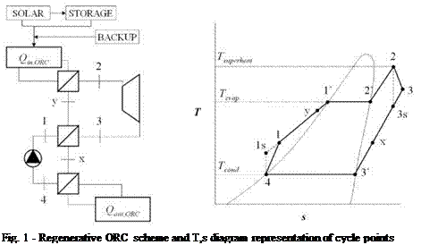 |
The power block is based on a regenerative Organic Rankine Cycle according to the scheme and T — s diagram presented in figure 1.
R245fa is the substance considered as working fluid of the ORC in this work. Although this fluid yields lower values of the ORC thermal efficiency, when compared, e. g., to toluene or hexamethyldisiloxane [8], it presents zero ozone depletion potential or low flammability properties, environmental, health or safety issues accounted in the fluid selection process, considering the aim of the project.
Considering R245fa, the operating parameters that optimize ORC thermal efficiency in both cycles 2 and 3[5] top temperature conditions are given in Table 1. These values were determined considering typical values for regenerator effectiveness (0.80) [9-12] and vapour turbine efficiency (0.75). The latter is the estimated value for low power output ORC units (100-500 kW) [12]. Operating conditions presented in Table 1 are considered as full load ORC operating conditions.
|
Table 1. Optimized ORC operating parameters for cycles 2 (C2) and 3 (C3) (Л = 0.75; Vr = 0.75; eR = 0.80; Tcond = 30 °C)
|
B. Schmitt*, K. Vajen and U. Jordan
Kassel University, Institute of Thermal Engineering, 34125 Kassel (Germany)
* Corresponding Author, solar@uni-kassel. de
Abstract
The generation of process heat for industrial applications seems to be a promising market for solar thermal systems. Processes in several industrial sectors consume high amounts of thermal energy at a low to medium temperature level. These boundary conditions are given in the food and beverage industry, especially in breweries. In this paper, basic information are given for the implementation of solar heating systems in breweries.
Using the Hutt brewery in Kassel (Germany) as example, the diversity in brewing processes is shown. Although all breweries consume large amounts of thermal energy for the wort production, every single brewery has to be analysed relatively detailed. To estimate a reasonable integration of a solar heating system, a detailed water and energy balance has to be drawn. The strong influence of the existing or available installations on a solar heating system is shown by two different concepts for the Hutt brewery. Therefore, it will be difficult to develop general guidelines for a suitable implementation of solar heating systems in breweries.
Keywords: solar process heat, industrial processes, brewery, energy efficiency
1. Introduction
By the year 2006, approximately 128 GWth of solar thermal collectors had been installed worldwide. Most of the installed systems were used for domestic hot water preparation, space heating or swimming pool heating [1]. So far approximately 90 solar heating plants with a total capacity of 25 MWth were used for industrial applications, which is a nearly negligible share of 0.02%. Within the framework of IEA SHC Task 33/IV, the potential for industrial applications within the EU 25 was estimated to be between 100 and 125 GWth. This huge potential is based on two facts: Firstly, the industry sector consumes nearly 30% of the total primary energy consumption in the EU25 and secondly, a significant share of the heat consumed in this sector is in the low and medium temperature range [2]. Approximately one third of the total industrial heat demand is required at temperatures below 100°C and nearly 60% at temperatures below 400°C. In some of the industrial sectors, such as food, wine and beverage, transport equipment, textile, pulp and paper, the share of heat demand below 250°C can be as large as 60% [3].
The food and beverage industry is one of the key sectors for solar heating, since processes such as cleaning, drying, pasteurisation, sterilisation or boiling take place at a low temperature range and the overall energy consumption is large [4]. To realise a significant implementation of solar heating systems within this industry sector, it has to be analysed which part of the high heat demand at a low and medium temperature level could be provided by solar heating systems, how to
integrate these systems in already existing processes and finally, how to transfer this knowledge to similar processes or other sectors.
Within the food and beverage sector, breweries show a large heat demand at relatively low temperature levels, but also a large potential for heat recovery. The brewing sector is furthermore interesting because of the large amount of breweries in Europe and especially Germany. All over Europe, there are more than 2,800 breweries, nearly half of them is located in Germany. Almost 85% of all German breweries are small and medium sized companies (SME) with an annual beer production of 50,000 hl or less [5]. In 2006, about 4.3 TWh (15.5 PJ) of energy was consumed in almost 1,300 German breweries, only one fourth of the consumed energy was electricity [6].
David Loureiro, Maria Joao Martins, Jose Antonio Santos, Antonio Nogueira,
Jorge Cruz Costa, Luis Pestana, Edgar Atai’de
INETI, Department of Renewable Energies, Campus do Lumiar, 1649-038 Lisbon, Portugal
E-mail: david. loureiro@ineti. pt
The aim of this work is to contribute to the discussion of the methodology that leads to a better systematization of the knowledge on solar drying. Based on a case study for the lumber industry, the options and solutions adopted will be reported, along with their evaluation criteria and existing or developed tools. The kilns have 50 m3 interior capacities and proved the capability to dry maritime pine 27 mm thick, from green to 12% moisture content in about 33 days. The performance of the drying process has a significant seasonal and weather dependence, so an interactive control system is essential in order to profit as much as possible from the favorable exterior conditions.
The use of solar energy for drying purposes is in general meant to save drying costs, primary energy and to reduce CO2 emissions. For these reasons over the last few decades, several solar drying systems have been described for agriculture and forest products, many of them reported in Europe [1,2] where the performance of the drying process has a significant seasonal dependence. This trend has been triggered by the promotion of rational energy use and renewable energies sources by European Union next to industrial manufactures.
Although several innovative versions and applications have been reported, there is an important lack of reliable information on the energy efficiency of solar energy based driers which is essential to gather in order to establish such driers as an acceptable industrial alternative when compared with traditional types based on fossil sources of energy.
The aim of this paper is to contribute to a discussion on the methodology that leads to a better systematization of the knowledge about the solar drying area, namely on the energy efficiency, wood quality, drying duration and drying costs. Based on a case study for the lumber industry, the options and solutions adopted will be discussed, along with their evaluation criteria and existing or developed tools.
The receiver is operated with a variable mass flow to maintain the design hot air temperature of approx. 680°C. In operation, first the thermal storage is charged to a certain level to have a backup for compensation of less or no solar radiation. In times of high solar radiation the receiver provides enough heat to charge the storage and to produce steam. To charge the storage the excess hot air mass flow enters the storage from the top and dissipates its heat to the storage mass. When the receiver is generating less hot air than required (e. g. due to cloud transients) the differential hot air flow is provided by a discharge flow through the storage entering at the bottom [3].
The concept of a hybrid tower plant is shown in Fig. 1. To achieve the gas parameters at the inlet of the HRSG for nominal load even by less solar radiation a channel burner is included. The burner heats up
 |
the preheated air from the receiver to the desired temperature. Instead of using a channel burner a gas turbine can be combined with the system. The gas turbine is in a parallel position to the receiver. The exhaust gas of the gas turbine is mixed with the air from the receiver to get the nominal mass flow at a high temperature. After the HRSG the exhaust gas is recirculated to the receiver or can be passed to a stack. This hybridisation concept has the advantages of combined cycles, like a high efficiency, and an additional power production by the gas turbine. As fuel natural gas or biogas (to maintain the status of the plant using renewable energies) can be used. In addition the hybridisation concepts can be used in different operation modes. The burner or the gas turbine can be operated parallel or in turn with the solar air receiver. Parallel means that on a day with less solar radiation both components can provide the heat for the HRSG at the same time. In the other operation mode the hybrid component is only switched on in the night or at times of no solar radiation.
The optimal orientation of a collector (e. g. south, tilted according to the latitude) is often not to choose. To take into account the local conditions (roof slope, roof orientation, site orientation) it often needs a compromise. CPC vacuum tube collectors have the advantage that they can compensate an unfavourable orientation with the smallest additional collector area. In an extreme case with east orientation flat plate collectors need 90 % more area. With vacuum tube collectors this would be only 40 %. This is because of the better Incidence Angle Modifier (IAM) and the higher efficiency factors with small irradiation as usual with unfavourable roof orientations as well as in the morning and evening.
Linked to IEA-SHC Task 33, several new development activities on process heat collectors were carried out. In order to give a short overview on these developments, three categories may be introduced:
• vacuum tube collectors and improved flat-plate collectors: double-glazed flat plate collectors with anti-reflection glazing and hermetically sealed collectors with inert gas fillings, or a combination of both. These collectors are installed in a fixed orientation; no tracking of the collectors. Full utilisation of the global solar radiation.
• stationary (i. e. non-tracking) low-concentration collectors: stationary CPC type collectors. The concentration factor is low (approx. 1.5 … 2) in order to avoid tracking. The acceptance angle of the concentrating reflectors reduces the utilisation of the solar radiation.
• concentrating tracking collectors: parabolic trough, Fresnel collectors or Fixed Mirror Solar Collectors (FMSC) with small aperture widths. Only the direct solar radiation is utilised.
The booklet (see Fig. 2) can be downloaded from http://www. iea-
shc. org/publications/downloads/task33-Process_Heat_Collectors. pdf. It is an outcome of the Subtask C of the SHC-IEA-Task 33. In a first part, a general description of the following different collector technologies is given :advanced flat-plate collectors, evacuated tube collectors, CPC-collectors, parabolic trough collectors, linear concentrating Fresnel collectors and finally concentrating collectors with stationary receiver.
In the second part of the booklet information from the developers of 14 different process heat collectors is given on their specific collectors. These developers were (some more, some less) linked to the work of the Task.
Solar
IEA SHC-Таєк 33 and SolarPACES-Task IV Solar Heat for Industrial Processes
State of the Art within Task 33/IV
Edited by Werner Weiss. AEE INTEC. Austna
and Matthias Rommel, Fraunhofer ISE Germany
Fig. 2. The booklet ‘Process Heat Collectors’ is an outcome of IEA-SHC Task 33. It has 56 pages and can be downloaded at www. iea-shc. org
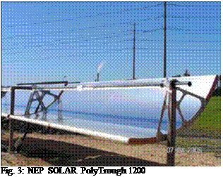
Just in order to give some impressions of new concentrating collector developments aiming at higher operating temperatures, fig 3 shows an example for a parabolic trough collector which is under
 |
 |
development in Australia, the NEP SOLAR PolyTrough 1200. The mirror panel carriers are made of polymeric composite materials and are light weight. The aperture width of the trough is 1.20m, the length of a trough panel is 6m and a standard module has a length of 24m. The focal length of the reflector is 0.65m and the geometrical concentration ratio is 45. Solar tracking is achieved trough a microprocessor controlled stepper motor and reduction drive. The target operating temperature is 150 to 275°C, depending on the application. Generally, the constructive challenges to be met are sufficient stiffness with respect to bending, sufficient precision of the reflector geometry and a general long term stability of all components and the total construction.
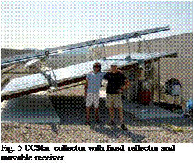 |
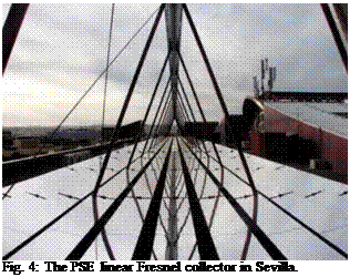
Figure 4 shows a picture of a linear Fresnel collector developed by the company PSE AG, Freiburg. This collector was installed in Sevilla, Spain in 2008. It is already the third collector which PSE installed, after two testing collectors erected and investigated in Freiburg, Germany and in Bergamo, Italy. The collector aims at the same operating temperature range. In Bergamo, the collector is supplying heat to an NH3/H2O absorption chiller. The width of a single reflector is 0.5m, the total width of the collector is and the length of one module is 4 m. The largest of these installations is the 176 kWth collector in Seville Spain shown in the picture, where the collector powers a double effect LiBr chiller.
In these two examples tracking of the sun is achieved by moving the reflector. But it is also possible to have the reflector installed in a fixed position and then move the receiver. The concept is called "Fixed Mirror Solar Collector (FMSC)". Figure 5 shows an example: the CCStaR-collector (Concentrating Collector with stationary Reflector) which is still under development by the company TSC, Barcelona and the Universitat de les Illes Balears, Palma de Mallorca, Spain.
It is interesting to point out that building — and roof-integration is an important and challenging aspect for the application of large process heat collector fields (which in the end mainly will have to be installed on buildings and factory roofs). Also under this aspect the different collector technologies offer different advantages and application chances so that it is positive to have different possibilities available.
Please have a look on the booklet for more information on these collectors and on all the others.
If the simulation results of the reference cases are plotted as a function of the utilization ratio, all simulated points almost fall onto a single line that is decreasing with increasing utilization ratio. Towards the left, the collector area is increased, to the right it is decreased. The larger the collector area and the smaller the heat demand is, the higher is the solar fraction. High levels of utilization signify low degrees of solar fraction and vice versa. The specific yield shows the well-known behavior running contrary to the solar fraction.
Figure 5. Nomogram to determine the collector area and the solar fraction and at the same time the specific
collector yield. The graph is based on a specific storage tank volume of 50 liters per m2 of collector area.
The only points that are slightly lower than the overall trend curve are the ones that represent Case 4 (with high internal loads). In this case, the internal loads occur always during the daytime (i. e. at
the same time when there is solar yield). Because of the internal loads there is no heat demand during working hours but only at night and on the weekends. Therefore, the solar energy can never be used directly in the building but always has to be stored for later use. Therefore, more storage tank losses occur compared to a building that has space heating demand also during the day.
The light-colored areas in the diagram show the typical range of solar fractions and specific collector yields that are reached with systems using the storage tank concept. Particularly in industrial buildings, economic considerations dominate that is why systems should be designed in accordance with the optimum ratio of cost-to-benefit (orange area, between approx. 15 and 40% solar fraction). Degrees of solar fraction of less than 15% are outside the cost-to-benefit optimum since the (slight) rise in the specific yield does not make up for the higher specific system costs of a smaller solar thermal system and would thus lead to higher solar heating costs.
Handling of the Nomogram: The nomograms can be used in two different ways:
Determination of solar fraction: If the annual heating requirement has been determined, the utilization ratio for a particular planning project can be calculated by dividing this value by the collector area. If a vertical line is drawn through the point of the determined utilization ratio, then the intersection with the curve of the solar fraction is obtained and the value can be read off on the left ordinate. The same is true for reading off the specific yield on the right ordinate.
Determination of collector area: If a desired solar fraction constitutes the starting point then a horizontal line can be placed at the corresponding height. The point intersecting with the curve of the solar fraction then allows the necessary utilization ratio to be read off on the abscissa. The necessary collector area is obtained by dividing the annual heating requirement for space heating by the utilization ratio. The solar storage tank volume of 50 l/m2 is directly proportional to the collector area.
Considering the top cycle temperatures prescribed for both cycles 2 and 3, different collector prototypes are under development in the framework of project, namely: an evacuated CPC for cycle 2; and a linear Fresnel concentrator for cycle 3.
At this point, a preliminary assessment of the evacuated CPC allows an early estimation of its efficiency parameters (steady-state) according to the values presented in Table 2.
|
Table 2. Estimated efficiency parameters (steady-state) for Cycle 2 evacuated CPC collector
|
A ray-trace based assessment allows a preliminary estimation of longitudinal and transversal incidence angle modifier (IAM) values according to Table 3.
|
Table 3. Estimated transversal and longitudinal IAM values for Cycle 2 evacuated CPC collector
|
Instantaneous power calculations performed after cycle 2 conditions and estimated CPC parameters follow the corrected methodology presented in [14].
Regarding cycle 3, the present state of development of the linear Fresnel concentrator does not allow an early assessment of both optical and thermal performance (information available to the project consortium within next spring, according to project planning).
Nevertheless, in the present paper the assessment of the POWERSOL technology for top cycle temperature conditions of cycle 3 is made after thermal and optical parameters of a commercial parabolic trough collector (PTC), the LS-3 model (used between 1984 and 1990 in the Mojave desert, CA, USA solar thermal power plants, e. g.).
LS-3 PTC efficiency and IAM follows the parameters described in [15], with thermal loss coefficient calculated after the polynomial expression presented in [16]. Instantaneous power calculations for LS-3 PTC followed ‘EW’ tracking configuration neglecting diffuse or ground reflected radiation components (reasonable simplification in view of the 26.2 concentration factor).