Как выбрать гостиницу для кошек
14 декабря, 2021
Сегодня каждый, кто собирается в отпуск и не знает, с кем оставить своего котика или кошку, может во[...]
The optical properties of the cerium oxide particles were calculated from the Mie-scattering theory [4]. From this theory the spectral absorption, scattering, and extinction cross-sections, as well as the scattering phase function can be calculated, with the complex refractive index of the particle material m, and particle radius rp as inputs. The complex refractive index of cerium oxide was
taken from different sources. From the papers by Ozer [5], and by Wiktorczyk and Oles [6], the optical properties for the visible and near IR were obtained. An expression for the IR properties CeO2 was taken from Santa et al. [7]. These latter authors fit the experimental reflectance values by using a quasi-harmonic damped multiple- oscillator model for the dielectric function.
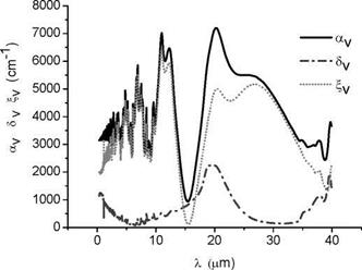
We consider particles of 5 pm radius. The spectral volumetric extinction, absorption, and scattering coefficients (ay, Sv and B, v respectively), are shown in Fig.1. These coefficients are given by
av = Cext,, / V Sv = Cabs,, / V £, = Cscatt,, / V (3)
Where Cext, ,, Cabs, , and Cscatt, , are the spectral extinction, absorption and scattering cross-sections, respectively, and V is the particle volume.
|
Fig. 1. Spectral volumetric attenuation, absorption, and scattering coefficients for particle radius of 5 pm. |
As seen on the graph, the extinction of radiation by these particles is mainly due to scattering; they are not very absorbing. Actually two main extinction peaks are visible, at 11 and 20 pm wavelengths. The first, one corresponds to resonance effects, while the second is due to absorption.
|
fvC |
|
abs,, |
|
V-1 |
|
Px |
|
(4) |
|
fvC |
|
ext,, |
|
V-1 |
|
fvC |
|
scatt,, |
|
V-1 |
The absorption (к), scattering (о) and extinction (ДО coefficients of the gas/particle fluidized medium are calculated from the spectral cross sections of the particles by
where fv is the particle volume fraction.
The phase function from Mie — scattering theory, as a function of the cosine of the scattering angle, is shown in Fig. 3. As seen from this graph, the particles scatter radiation mainly in the forward direction, for the UV, Vis, and near — IR, while for the far — IR they have an almost isotropic scattering (28.8 mp), with a slightly backward preference (38 mp).
1.1 TCM reactor system
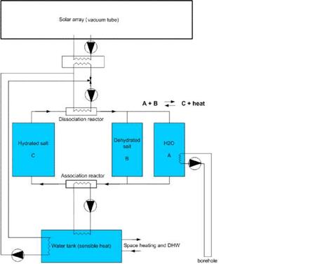 |
A parametric study was carried out for a TCM system for seasonal storage. A schematic layout of this system is shown in Fig. 2. A 200 liter water tank was added to the system in order to lower the power demands for the TCM storage. In this way, the water tank is used to supply peak power (e. g. shower peaks), while the TCM storage can recharge the water tank afterwards at a lower power level. The collector system is designed in such a way that the water tank is preferentially loaded. Only if the water tank has reached its maximum temperature, the TCM storage is charged with the excess heat of the solar array. The TCM storage consists of 3 vessels: vessel C containing the hydrated salt, vessel B containing the dehydrated salt and vessel A containing the water vapour (in condensed form). On charging the storage, the hydrated salt from container C is fed to a dissociation reactor that is heated by a vacuum collector array, whereby the water vapour is released from the salt. The hot dehydrated salt is fed to B and the water vapour to A, where it condenses. On discharging the storage, the dehydrated salt is fed to an association reactor, where water vapour is again absorbed and the released heat is transferred to a water storage. The water vapour is produced by evaporating the water in tank A by means of heat from the borehole.
1.1. How it works
The concept of a Dual Solar Pond (DSP) settles in the existence of two ponds one near the other that can work alternatively. They will be used as Solar Ponds at different times. In this paper we will consider the use of unused marine salt works for building the ponds, and we will consider a pond with a medium size SZ of 1 m and a NCZ of 1 m making a pond with a total depth of 2 m which is relatively easy to build in old marine salt works.
The single operation consists in create the gradient zone in order to establish the pretended NCZ. With these dimensions a simulation made with the parametric model presented in [7] points to a 21 days start up. For the same conditions but with a deeper SZ (3m), a conventional pond will need about 57 days. During the following months the DSP will work without maintenance until its NCZ degradation. Some time before the second marine salt work must be prepared to run as a Solar Pond. All this is shown in Figure 5.
Then DSP concept consists in recovering traditional marine salt works that will act as two alternating Solar Pond basins. When the first one begins the extraction energy mode the other is at stand by. When the first begins to have instability problems the second needs to be built in. In this way Solar Pond monitoring results to be very simplified. One must only predict when a Pond undergoing instability (not acting more as a Solar Pond) in order to begin, with same advance, to fill the other marine salt work.
The present work shows how to make this prediction concerning the dynamics of the whole process, including energy extraction to Aquaculture applications.
Per Alex Sorensen,1* , Leo Holm 2 and Niels Aage Jensen 2
1 PlanEnergi, Jyllandsgade 1, 9520 Skorping, Denmark 2 Marstal Fjernvarme, Jagtvej 1, 5960 Marstal * Corresponding Author, pas@planenergi. dk
Abstract
In 1996 Marstal Fjernvarme (Marstal District Heating) established 8.000 m2 solar collectors that covered 13% of the yearly consumption. The solar fraction in later built district heating plants goes up to 25% covering the total summer load, but several district heating companies especially natural gas fired combined heat and power plants want a higher solar fraction in order to replace expensive natural gas. Therefore new projects with solar fractions of 50% are designed and are expected to be implemented in 2009. Design calculations show that the production price for heat from solar thermal plants with 50% solar fraction can compete with heat prices from natural gas fired CHP plants.
This paper explains the Danish development in solar thermal plants for district heating from 19962008 and gives an opinion on future possibilities for solar district heating and cooling in Denmark and Europe.
In particular nitrate and nitrites and their mixtures promise to be suitable PCMs, if requirements such as handling and steel compatibility are taken into account. Table 2 shows that the number of nitrates and their mixtures, suggested in literature is limited. Hence, the aim of this work it to identify from literature and by own measurements potential binary mixtures of nitrites and nitrates. Table 3 summarizes relevant properties of selected alkali nitrates and alkali metal nitrites which were considered in this work. Due to their hygroscopic behavior, handling of the alkaline-earth nitrates Ca(NO3)2 and Mg(NO3)2 is difficult. Hence, these nitrates were excluded.
|
Table 3. Selected alkali nitrates and alkali metal nitrites in this work [1,14,31-33]
|
In this work, a comprehensive literature survey regarding the minimum melting temperature of the 21 binary alkali nitrate/nitrite systems was carried out [4,34-44]. Table 4 summarizes the result of this survey. Except for a few binary systems, melting enthalpy data of these systems are not known. Also, as can be seen some temperatures could not be identified (Table 4). Hence, additional experiments were carried out with particular reference to temperatures around 170°C,
since this temperature is not covered by known systems. The methods and results of the experiments are described in the next section.
|
LiNO.3 |
NaNO.3 |
KNO3 |
Sr(NO3)2 |
Ba(NO.3h |
NaNO2 |
|
|
LiNO.3 |
||||||
|
NaNO.3 |
193°C |
|||||
|
KNO3 |
ж 137,147°C |
220°C |
||||
|
Sr(NO3)2 |
249°C |
295°C |
275°C |
|||
|
Ba(NO3)2 |
244°C |
290°C |
287°C |
564°C |
||
|
NaNO2 |
ж 149,156°C |
227°C |
141°C |
n. a. |
n. a. |
|
|
KNO2 |
108°C |
149°C |
316°C |
n. a. |
170°C |
225°C |
|
Table 4. Secondary literature data of the minimum melting temperature of 21 binary alkali nitrate/nitrites. |
|
Two minimum melting temperatures |
There were five PCM related projects included in IEA SHC Task 32. A summary of these projects is given in Table 1.
Three projects dealt with macro-encapsulated PCM containers in water stores. All of these projects include the development of TRNSYS models for the PCM stores:
• At Lleida University, Spain, bottles and filled up heat exchangers of PCM material with graphite matrix for the enhancement of the heat conduction and increase of power input/output were tested. Applications are free-cooling and DHW tanks.
• At the University of Applied Sciences Western Switzerland in Yverdon-les-Bains/Switzerland a parametric study for the use of PCM in heat stores embedded in aluminium bottles for solar combisystems was carried out.
• The Institute of Thermal Engineering at Graz University of Technology performed tests and simulations with different PCM materials encapsulated in plastic tubes and steel containers for stores for conventional boilers to reduce the number of start-stop cycles of the burner.
The two other projects are slightly different:
• At the Department of Civil Engineering, Technical University of Denmark the use of super cooling of PCM materials for long-term heat storage was investigated with simulations. This project showed that a 10 m3 only PCM seasonal storage using the supercooling effect is theoretically possible. Experimental setup assessed some assumptions on heat transfer in a bulk PCM tank
• The Institute of Thermal Engineering at Graz University of Technology performed tests and simulations with PCM-slurries of microencapsulated paraffins for stores for conventional boilers to reduce the number of start-stop cycles.
The above project is also dealing with heat exchangers immersed in PCM material Table 1. Summary of prototype storage units studied in Subtask C.
|
Type of Technology |
Material |
Stage of Development |
Investigating Institute |
|
PCM seasonal storage using subcooling |
Na(CH3COO)3 H2O |
Lab prototype; Simulation model for store developed and seasonal simulations of the system were performed |
Technical University of Denmark (DTU), Denmark |
|
Macroencapsulated PCM in storage tank |
Na(CH3COO)3 H2O + graphite |
Lab prototype; Seasonal simulations of the system were performed, using the model developed by the Institute of Thermal Engineering, Graz Unviersity of Technology |
University of Lleida, Spain |
|
Macroencapsulated PCM in storage tank with integrated burner |
Na(CH3COO)3 H2O + graphite |
Lab prototypes; Simulation model for store developed and validated; Seasonal simulations of the system were performed according to the reference conditions from Subtask A |
University of Applied Sciences Western Switzerland (HEIG — VD), Switzerland |
|
Microencapsluated PCM slurry |
Paraffin, |
Lab prototypes, Development of simulation models for a store filled with slurry with various internal heat exchangers and flow/return pipes and an external heat exchanger with PCM slurry on one or both sides. |
Graz University of Technology, (IWT — TU Graz), Austria |
|
Macroencapsulated PCM in storage tank |
Paraffin, Na(CH3COO)3 H2O with/without graphite |
Simulation model for store developed and validated; Seasonal simulations of the system were performed for various hydraulic schemes for heating systems in order to analyze the reduction of the boiler cycling rate compared to water stores. |
Graz University of Technology, (IWT — TU Graz), Austria |
|
Immersed heat exchanger in PCM |
Na(CH3COO)3 H2O without graphite |
Simulation model for store developed and validated; Seasonal simulations of the system were performed for various hydraulic schemes for heating systems in order to analyze the reduction of the boiler cycling rate compared to water stores. |
Graz University of Technology, (IWT — TU Graz), Austria |
• The Institute of Thermal Engineering at Graz University of Technology performed tests and simulations with a bulk PCM tank with an immersed water-to-air heat exchanger for conventional boilers to reduce the number of start-stop cycles of the burner.
For a summary of these projects see Table 1; the main results are given in the following chapters.
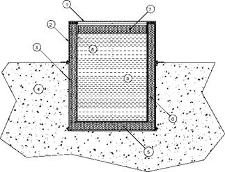
The solar energy collected by the solar panels will be stored in a water accumulator. For this prototype we considered a tank made from 200 mm thick high density EPS blocks, coated inside with a watertight reinforced PVC bag. This tank, which will be partially buried underground, will have a useful volume of 8m3. Figure 4 shows a side-section of this accumulator. For a AT of 20°C, the amount of energy stored in this tank will be 8.000 x 20 = 160.000 kcal = 186 kWh, roughly equivalent to 19 liters of diesel.
|
Fig. 4. Thermal energy storage tank: 1) transparent structured PC plate; 2) upper metal support structure; 3) lower (buried) metal structure; 4) soil; 5) bottom EPS plates; 6) side EPS plates; 7) top (floating) EPS plate; 8) inner reinforced PVC bag; 9) water. |
This energy corresponds to six hours of energy consumption under local extreme temperature conditions (Tin = 14°C and Tout = -1°C) for the considered prototype greenhouse. It also roughly corresponds to the daily average solar collection with these collectors during the colder months (160 kWh/day in January). If the collectors are not tilted back during periods with higher solar incidence, the temperature gain in the tank may easily exceed 40°C in a day.
As the root zone heating comes from water circulating at 30°C to 40°C, this tank is apparently suitable for this collector area. Warmer water inside the tank, besides increasing heat losses, decreases collector efficiency.
From these results we can assume that, in our climate conditions — temperature and radiation — the energy gain from a set of 3 x (36 m2) solar thermal panels installed inside a simple 300 m2 greenhouse glazed with structured PC plates, can exceed its needs if thermal properties are optimized. Therefore, a single module like this can eventually supply energy to one or two more standard modules with equivalent area.
[1] SolTerm5 (2007) — Analise de Desempenho de Sistemas Solares Termicos e Fotovoltaicos, INETI,
Lisbon
[2] W. J. Roberts (1997, 2005). Environmental Control of Greenhouses, CCEA, Center for Controlled Environment Agriculture, Cook College, Rutgers University.
[3] Dr. Gene A. Giacomelli (2002). Considerations for Energy Management of Greenhouse Heating and Cooling, University of Arizona
[4] Online Conversion, Blue Sparks Network — www. onlineconversion. com
[5] Suntrek Industries, Irvine, USA — www. suntreksolar. com
[6] W. J. Roberts, D. R. Mears, J. C. Simpkins, J. P. Cipolletti (1981). Movable Thermal Insulation for Greenhouses, Biological and Agricultural Engineering Department, Rutgers University.
[7] William J. Roberts, D. R. Mears (1980). Paper n° 80-4027, Floor Heating of Greenhouses, Biological and Agricultural Engineering Department, Rutgers University.
[8] Steve Diver (2002). Root Zone Heating for Greenhouse Crops — ATTRA, U. S. Department of Agriculture
The authors thank Professor Dr John Rekstad, from the Physics Department of Oslo University, for his help in the project discussion.
In an open sorption storage system air is transporting water vapor and heat in and out of the packed bed of solid adsorbents (see figure 7) or a reactor where the air is in contact with a liquid desiccant. In Desorption mode a hot air stream enters the packed bed or the reactor, desorbs the water from the adsorbent or the salt solution and exits the bed cooler and saturated. In adsorption mode the previously humidified, cool air enters the desorbed packed bed or the concentrated solution. The adsorbent or the solution (or absorbent) adsorbs (or absorbs) the water vapor and releases the heat of sorption. The air exits warm and dry. In case of a solid adsorption it can be very hot. In case of a liquid absorption the dehumidification of the air is the main purpose.
The desorption energy QDes is the energy input to the thermochemical storage system, whereas the heat of adsorption energy QAds can be used for heating. The heat of condensation QCond can be additionally used, if it is available on a usable temperature level, which is depending on the inlet air conditions. The energy for evaporation QEvap has to be available at a low temperature level, which can not be used otherwise (right scheme of figure 7). The desiccant cooling process is based on the dehumidification of the air during the adsorption mode only.
Thermal energy storage is achieved by separating the desorption step (charging mode) from the adsorption step (discharging mode). After desorption the adsorbent can theoretically stay in this desorbed state, being referred to as charged in the following, without any thermal losses until the adsorption or absorptions process is activated [5], [6].
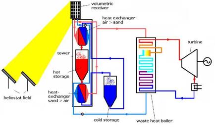
Concluding from the simulation results in section 2.2 and pressure drop measurements (not discussed above), the optimal sand grain size with respect to heat transfer and heat exchanger auxiliary energy demand is in the range 2-3 mm. With larger grain size the effectiveness of heat transfer will drop whereas for a lower sand grain size the increasing pressure drop will lead to substantial auxiliary energy demand or a high heat exchanger volume, if the air velocity is decreased.
For selection of sand grain size the fluid bed cooler as shown in Fig. 1 might be a limiting element. Larger grain sizes lead to increasing erosion on the heating surfaces of the fluid bed cooler, so that the sand grain size is presumably limited to 1 mm.
Larger sand grain sizes can be used when the storage concept is modified as shown in Fig. 7.
|
Fig. 6 Modified storage concept for coarse sand/grit |
Differing from the sand storage concept shown in Fig. 1, this storage concept does not require modifications of the steam circuit and equals with the conventional packed bed storage concept using a waste heat boiler.
Elements are used from the sand storage concept including air-sand heat exchanger, hot and cold storage tank and the sand transport system. In view of the thermal stresses in case of high change of operation modes, two separate air-sand heat exchangers for storage charging and discharging could be advantageous. In contrast to the storage system shown in Fig. 2, for storage discharge the heat is transferred again back in the heat exchanger from sand to air.
Which of the two storage concepts using sand is the better one will be evaluated in a cost analysis when more precise data of heat exchanger effectiveness are available.
The project was supported by the German Ministry of Education and Research (BMBF) through its FH3 programme.
|
AV |
Surface area per volume |
Ullli m2/m3 |
T |
Temperature |
U1111 °C |
|
cP |
Heat capacity |
J/(kgK) |
v |
Velocity |
m/s |
|
D |
Width of sand bed |
m |
V |
Volume flow |
m3/s |
|
h |
Convective heat transfer |
W/(m2K) |
є |
Porosity |
|
|
coefficient |
SHX |
Heat exchanger effectiveness |
|||
|
H |
Height of sand bed |
m |
p |
Density |
kg/m3 |
|
k |
Heat conductivity |
W/(mK) |
p |
Density |
kg/m3 |
|
m |
Mass flow |
kg/s |
nDyn |
Dynamic viscosity |
Pa s |
|
Q |
Heat flow |
W |
К |
Permeability |
m2 |
|
Indices: |
|||||
|
A |
Air |
S |
Sand |
[1] S. Warerkar, S. Schmitz, J. Gottsche, B. Hoffschmidt, Air-Sand Heat Exchanger for solar tower power stations, 2nd International Renewable Energy Storage Conference (IRES II), November 2007, Bonn, Germany
[2] N. Siegel, G. Kolb, J. Kim, V. Rangaswamy, S. Moujaes, Solid particle receiver flow characterization studies, Proceedings of Energy Sustainability 2007 conference, ASME, June 2007, Long Beach, California
[3] H. Fricker, Regenerative Thermal Storage in Atmospheric Air System Solar Power Plants (ed: A. Steinfeld), Proceedings of the 11th International Symposium on Concentrated Solar Power and Chemical Energy Technologies, 2002, Zurich, Switzerland
|
Figure 15. CTCFR Energy Reponse (цт) |
|
Figure 17. CTVFR Energy Reponse (пш) |
|
Figure 19. VTVFR Exergy Charge Ratio (nCR) |
|
Figure 16. CTCFR Exergy Charge Ratio (nCR) |
|
Figure 18. CTVFR Exergy Charge Ratio (nCR) |
|
Figure 20. VTVFR Exergy Charge Ratio (псд) |
 |
 |
Figures 15 to 20 show results from the simulations of the CTCFR, CTVFR, and VTVFR cases. The duration of each simulation was in the order of 4.5 to 5.5 hours. Only the “hot” tank has been simulated in these tests.
The combination of the Energy Response and Exergy Charge Response curves indicate that the original STTS design, Tank 1, produces a high rate of mixing in all cases studied. This is evidenced by a slow climb of the Exergy Charge Response along with an early decline of the Enerhy Reponse. This observation was also evident in the initial study by the authors [6]. The high values of the цш curves during the VTVFR simulations, however, illustrate the difficulties in assessing closed-loop systems using only First Law characterization methods.
From the Exergy Charge Response curves, we see that Tanks 6 and 7 have initially very high values of П(ск. This must be attributed to the tanks’ separation of the internal volume into smaller nodes, as the incoming fluid has less of a distance to travel downstream before a thermocline can develop. Tank 7, which incorporates the slotted plenum at the inlet region, exhibits only a slight performance advantage over Tank 6. We also see, however, temporal dips in the curves for both Tanks 6 and 7, most evident in Figure 16. These dips occur at each instance that hot fluid reaches a new node, initially mixing until a new thermocline develops. Tank 4, with a less immediate increase to its n^CR curves eventually outperforms Tanks 6 and 7 once its thermocline develops. It should also be noted that the eventual fall of the Energy Response also occurs at a lower rate for Tank 4, indicating improved energy storage characteristics. Tanks 2 and 3 illustrate the storage effectiveness gained solely from repositioning the STTS inlets, irrespective of a center baffle. For the Operational Exergy Charge Response in Figure 20, we can see the impact of the system’s flow rate limitations. This characteristic will be discussed further in work currently in development by the authors. The assessment of Tank 5 will also be done within a future study.
This study has presented an early investigation into a new method for characterizing thermal energy stores using the 2nd Law of Thermodynamics. Although initial findings have shown that the new index, the Exergy Charge Response, may be useful in the assessment of thermal mixing at the initial stages of charging, a future study will continue to examine its applicability for various charging/discharging applications, as well as account for existing 2nd-Law characterization indices.
[1] Panthalookaran, V., (2007). CFD-Assisted Characterizationand Design of Hot Water Seasonal Heat Stores.
Ph. D. Thesis. University of Stuttgart, Germany
[2] Shah, L. J., and Furbo, S., (2003). Entrance Effects in Solar Storage Tanks. Solar Energy, 75(4) pp. 33748.
[3] Sibbitt, B., Onno, T., McClenehan, D., Thornton, J., Brunger, A., Kokko, J., Wong, B. (2007). The Drake Landing Solar Community Project — Early Results. Proceedings of the 2nd Annual Canadian Solar Buildings Research Network. Calgary, AB, Canada.
[4] Rysanek, A., Harrison, S. J., (2008). On the Characterization of Thermal Energy Stores using CFD: A Case Study of the Drake Landing Solar Community. Proceedings of the 3rd Annual Canadian Solar Buildings Conference. Fredericton, NB, Canada.
[5] Moran M. J., Shapiro H. N. (2004). Fundamentals of Engineering Thermodynamics. 5th Edition.
John Wiley and Sons, Inc., USA
[6] Krane, R. J., (1987). A Second Law Analysis of the Optimum Design and Operation of Thermal Energy Storage Systems. International Journal of Heat and Mass Transfer. 30(1) pp.43-57.
[7] Rosen, M. A., and Dincer, I., (2003). Exergy methods for assessing and comparing thermal storage systems,
Transport Phenomena in Energy systems and Processes. Wiley. UK. 27, pp. 415-30
[8] Haller, M. Y., Cruickshank, C. Streicher, W., Harrison, S., Andersen, E., Furbo, S. (2008). Methods to determine stratification efficiency of thermal energy storage processes — review and theoretical comparison.
Solar Energy. (in publication)
[9] Han, Y. M., Wang, R. Z., Dai Y. J., (2008). Thermal stratification within the water tank. Renewable and Sustainable Energy Reviews (in publication)