Как выбрать гостиницу для кошек
14 декабря, 2021
The liquid-side heat transfer correlation is valid for high Re numbers (see section 2.4). For the airside performance correlations used in the model, the validity range is determined by the range of heat exchanger geometrical parameters and operating parameters in the data base. These are (here shown only for dry surface):
For plain fins [10]: Reair = 300 — 11000, N = 1-6, Do = 6.35-12.7 mm, Fp= 1.19-8.7 mm, Pt= 17.7-31.75 mm, Pi = 12.4-27.5 mm.
For herringbone wavy fins [12]: Reair = not explicitly mentioned, but should be in a similar range as in the correlation above, N = 1-6, Dc = 7.66-16.85 mm, Pd = 0.3-1.8 mm, Fp= 1.21-6.43 mm, Pt= 21-38 mm, Pl = 12-33 mm.
Although a corrugation angle is one of the parameters in the correlation, its range is not given in
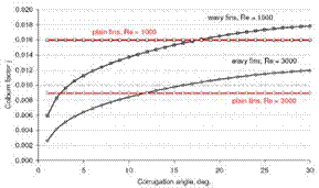
[12] . Additionally, wave height Pd or wave length xf are not considered in the correlation, although they have a considerable influence on heat transfer and friction coefficients at Re > Recritical [20]. Furthermore, the influence of the corrugation angle in the heat transfer correlation is inconsistent. For some geometrical parameter combinations heat transfer coefficient expressed in terms of Colburn factor increases with increasing corrugation angle as expected or stated by many investigations (cf. literature review in [20]), Fig. 1a. For other parameter combinations it does not, even having sometimes a clear optimum, Fig. 1b. Whereas the friction factor increases with increasing fin corrugation angle as expected, Fig. 2. Additionally, for some fin corrugation angle values the Colburn factor j and the friction factor f for wavy fins are smaller than those for plain fins (calculated according to [10]), Fig. 1 and 2. These effects are obviously caused by a complex structure of the correlation. Unfortunately, no other (“better”) correlations for wavy fin heat exchangers were identified in the literature, nor did Jacobi et al. [14] find any.
|
Table 1: Geometrical dimensions of the heat exchangers referred to in this paper.
|
 |
 |
Fig. 1. Influence of the fin corrugation angle on a Colburn factor j correlation [12] for two heat exchanger
configurations: (a) left HX 2, (b) right HX 3, see Table 1.
 |
 |
For comparison, values of the Colburn factor for plain fins [10] are also shown.
Fig. 2. Influence of the fin corrugation angle on a friction factor f correlation [12] for two heat exchanger
configurations: (a) left HX 2, (b) right HX 3, see Table 1.
All chosen airside correlations have similar accuracies. They describe about 90% of experimental heat transfer data (Colburn factor) and approx. 85% of friction factors within 15% error.
The flow friction usually contributes more than 90% of the airside pressure drop in a heat exchanger [18], so that the model accuracy regarding the airside pressure drop calculation is in a similar range as the accuracy of the airside friction factor correlation. An accuracy of equations for friction factor in tubes is not given in [19]. Thus, the model accuracy regarding the pressure drop calculation on liquid-side is unknown.
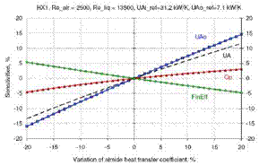
The heat transfer rate is not directly proportional to the airside heat transfer coefficient. Therefore, a differential sensitivity analysis was carried out in order to estimate the influence of the uncertainty of the airside heat transfer coefficient on the heat transfer rate. The results for the heat exchanger geometry HX1 (see Table 1) and two different ratios of UA values on liquid and air sides are shown in Fig. 3, where the airside heat transfer coefficient was varied up to 20%. The UAo value on the air side changes less than the Uo value, because the fin efficiency is negatively correlated with Uo. The overall UA value is less sensitive than UAo, but its sensitivity depends on the ratio of UAi and UAo. For both presented typical UAi and UAo ratios, the change in the heat transfer rate remains less than 5%, when the airside heat transfer coefficient varies within ±20%. Thus, the model accuracy regarding heat transfer calculation is within 5%, when the uncertainty of the airside heat transfer coefficient is less than 20% (at least for the investigated geometry).
 |
 |
Fig. 3 Heat transfer sensitivities on an airside heat transfer coefficient for geometry HX 1 and two different
ratios of UA values on liquid and air sides