Как выбрать гостиницу для кошек
14 декабря, 2021
In order to evaluate the system behaviour under different draw off volumes and to determine the maximum usable hot water over a whole year, several simulations have been carried with a collector tilt angle of 42° under the climatic conditions of Rome. It has been assumed that hot water is only needed in the evening in between 6.00 — 8.00 pm. The system is included into an existing hot water system consisting e. g. of a gas boiler for hot water and room heating or a simple electronic hot water boiler.
 |
An automatic tempering valve at the hot water outlet of the storage prevents the users from scalding themselves. A selector valve automatically takes the hot water from the backup heating if the hot water temperature turns below 45°C. Figure 6 shows a schematic drawing of the system.
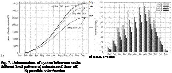
The daily draw off pattern was varied in the range of 120l/d.480l/d. As a first result of these variations it can be seen that the hot water draw off out of the 180l storage is limited to about 35,000l/a respectively the draw off gets saturated at about 240l/d, because of the climatic
conditions. With a draw off profile of only 120l/d, an annual solar hot water fraction of about 66% can be achieved. In terms of saved energy this equals a reduction of about 95l of fuel oil. With a hot water demand of 180l/d, it is still possible to cover nearly 50% of the annual hot water demand or an equivalent of 125l of fuel oil with only one collector of about 2m2 and a 180l storage tank.
The paper presents the implementation of a double mantle heat exchanger into the simulation environment CARNOT and first simulation results calculated with the new storage type.
The developed double mantle heat exchanger storage is based on the TRNSYS double mantle heat exchanger storage but was enhanced by the possibility of including user settable material and geometric data.
Concerning the system simulation, some “to dos” remain, like the validation of a modified “thermosiphonic pump”, which is able to calculate the fact of reverse thermosiphoning e. g. at night. In order to improve the system and to identify other main influencing variables, further simulation runs have to be carried out, e. g. with regard to overheating.
[1] S. Gurtner, F.-D. Treikauskas, W. Zorner: „Prufstand fur Thermosiphonanlage am Kompetenzzentrum Solartechnik an der Fachhochschule Ingolstadt“, 16. Symposium Thermische Solarenergie, Kloster Banz / Staffelstein (Germany), May 2006, p. 118 — 122.
[2] S. Brandmayr, W. Zorner: “Thermosiphon Systems: Market, State-of-the-Art and Trends“, 3rd European Solar Thermal Energy Conference (estec2007), Freiburg (Germany), June 2007, p. 182 — 188.
[3] N. N.: “Matlab/Simulink user manuals”, The Mathworks Inc., http://www. mathworks. com, Natick (USA), 2002.
[4] B. Hafner, J. Plettner, C. Wemhoner: “CARNOT Blockset: Conventional And Renewable eNergy systems OpTimization Blockset — User’s Guide”, Solar-Institut Julich, Aachen University of Applied Sciences (Germany), 1999.
[5] A. Carillo Andres, J. M. Cejudo Lopez: “TRNSYS model of a thermosiphon solar domestic water heater with a horizontal store and mantle heat exchanger”, Solar Energy, Vol. 72/2 (2002), p. 89 — 98.
[6] G. L. Morrison, D. B.J. Ranatunga: “Thermosyphon circulation in solar collectors”, Solar Energy, Vol. 24 (1980), p. 191 — 198.