Как выбрать гостиницу для кошек
14 декабря, 2021
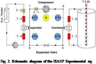
A schematic diagram is shown in Figure 2, depicting the main components of the ISAHP test rig. Table 1 lists the instrumentation and monitoring equipment used in the experiment, whose part numbers correspond to the schematic diagram.
|
Table 1 List of instrumentation used
|

The main components of the apparatus include: a nominal 1/3 HP single speed compressor, a thermostatic expansion valve, two flat plate counter-flow heat exchangers acting as the evaporator and condenser of the heat pump, a standard residential hot water tank (270 L), a variable speed pump and an auxiliary heater for simulating the solar collector heat input. R-134a was used as the working fluid for the heat pump cycle, and a 50 / 50% glycol/water solution by volume was used in the collector loop.
The collector loop operates in a similar fashion to that of a typical solar domestic water heating system. First, the glycol solution is pumped through the collector, or in this case the auxiliary heater, in a closed loop. The glycol solution absorbs energy through the “collector”, and a heat exchanger is used to extract the heat from the glycol, which acts as the evaporator of the heat pump loop. The R-134a superheated gas exits the evaporator and passes through the compressor, increasing in both pressure and temperature. The refrigerant then releases its heat and condenses through the natural convection heat exchanger, which delivers hot water to the storage tank. The R-134a liquid then passes through the thermostatic expansion valve, reducing its pressure before re-entering the evaporator.