Как выбрать гостиницу для кошек
14 декабря, 2021
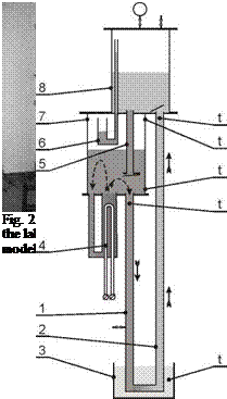
The schematic diagram of the laboratory installation and its photo are shown in Figs. 2 and 3. The warm and cold work vessels are made of cylinders and mounted one above another. The diameter and the height of the cylinders are 110 mm and 140 mm, respectively. Both cylinders are transparent and made of Plexiglas for visual observation. An electrical resistance heater with a capacity of 300 W was used as a source of heat. The heater had a temperature control for maintaining a few set-point temperatures. The control valve was made as a liquid seal. The heat exchanger (cooler) used for cooling the heat-carrier was located one metre below. The heat exchanger was made of a copper coil with a surface area of 0.15 m2 and placed into the cylinder vessel with a capacity of 7 litres filled with water. The vessel of the cooler was filled with water that was not running, but only accumulating heat leading to a temperature rise during the experiment.
The recorded data consisted of measurement of pressure inside the cold vessel and temperature measurements: at the top and the bottom of the inside warm vessel, at the descending pipe, at the
 |
up-flow pipe and at the vessel of cooler. Processes in the model are variable. It was decided to take measurements every 10 s since the duration of cycles was foreseen about 1 min and more.
 diagram of the passive heat transfer downward model:
4 — electrical heater, 7 — warm work vessel
5 — intermediate canal, 8 — cold work vessel,
6 — control valve (liquid seal), t — points of temperature
measurement
Experiments were done at a temperature of heat source of 33, 41, 49, 57 and 60°C.
The amount of heat carried by liquid heat-carrier from warm vessel during one cycle was calculated by using average temperature difference, tdescpipe measured at lower pipe and average minimum value of temperature, tup_flow pipe measured at up-flow pipe: