Как выбрать гостиницу для кошек
14 декабря, 2021
Two demonstration subprojects (Demo SP6a and Demo SP6b), among a total number of 12 in Polysmart project, are implemented in Portugal. Their description as well as the main differences between them is presented below.
3.1. Main characteristics of Demo SP6a
Subproject SP6a is designed to condition (heating and cooling) some office rooms (175 m2) equipped with fan coils at Ao Sol’s two-storey office building, and to heat up a DHW tank (0,4 m3) for the lavatory (showers included). A showroom (50m2) equipped with a small radiant floor as well as two fan coils (4-pipe distribution system) will also be supplied by the CHCP plant whenever needed during guided visits.
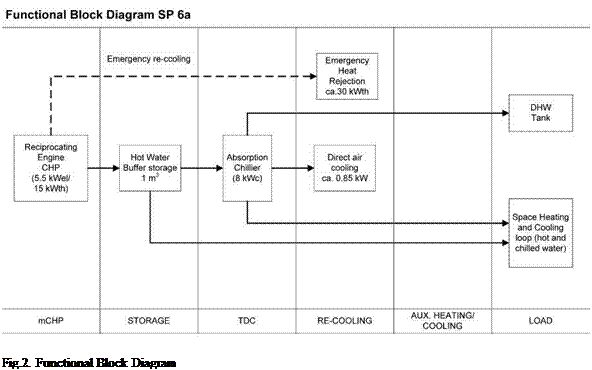
3.1.1. Functional Block Diagram and main Equipment
The two main parts of the Combined Heat Cool and Power system — pCHCP are the Combined Heat and Power unit — CHP (cogeneration) and the Thermally Driven Chiller unit (TDC).
The former is composed by a LPG fuelled, single-cylinder 4-stroke engine (approx. 580 cm3) which drives a 5.5 kWe nominal active power, water-cooled asynchronous generator [5]. Using this type of fuel, the standard CHP unit, operating at nominal conditions, has a thermal output of
around 12.5 kWth and the heat recovery circuit reaches a temperature of 84°C. Since this level of temperature is not high enough to drive the TDC at full capacity, the CHP unit is equipped with an additional condensing exhaust heat exchanger (condensing unit) that enables to further raise the TDC driving temperature to around 90 °C by recovering the heat from the flue gas (at around 150°C). Thus, in this particular case, the overall efficiency of the plant can rise to over 100% (in relation to LHV for the fuel used) depending on the environmental conditions and conditions of use.
The latter is an 8 kWcold ammonia/water prototype machine [6] with a nominal COP of 0.6 and direct air-cooling (no need for external heat rejection devices — cooling tower).
A hot water storage tank (1m3) is used as a buffer between the CHP and the TDC / heat sink. This buffer also allows modulating the water temperature of the heating distribution circuit, since the CHP has a fixed thermal output.
Since the return temperature from the TDC hot water circuit is higher than the maximum allowed inlet temperature of the CHP heat recovery circuit, the DHW tank can be heated up by the surplus heat trough an internal heat exchanger. Once the DHW is fully charged, an Emergency Heat Rejection unit (re-cooler) guaranties the inlet flow temperature, preventing the CHP from damage.
The chilled water circuit is not physically separated from the CHCP main circuit by any heat exchanger.
 |
The following figure shows the functional block diagram of the pCHCP plant.
The system can also use solar energy as thermal input, both in winter and in summer. The collectors will be CPC AO SOL and 30m2 are already installed for this purpose. The objective is to measure the contributions of the different sources in different operating modes, analysing the results and proposing the best operational and integration procedures.
Both yearly heating and cooling loads and peak power demand have been estimated using TRNSYS simulation tool [7]. The goal is to select the zones to acclimatize that lead to an optimum operating period of the CHCP plant.
The conditioned area of the building is around 175 m2 and the yearly specific cooling load is estimated to be circa 25 kWh/m2.