Как выбрать гостиницу для кошек
14 декабря, 2021
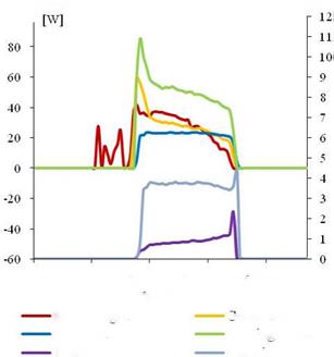
We are going to present the simplified model of our installation whose principle scheme is shown on the Fig. 1. The aim is to simulate the behaviour of our installation in order to get a better understanding of the comfort in the building hour by hour, taking account of external demands such as sunshine and attendance of the building. Therefore each component is modelled in the SPARK environment and integrated to the general model.
3.1. The solar collector field
 The solar thermal collector field is composed of 36 double glazing collectors (SchucoSol-U5 DG) specially designed for solar cooling systems. The collectors are spread over three loops of ten collectors plus a loop of six collectors. The four loops are installed in parallel. Before modelling the solar collector field, we have to carry out a “macro class” which will represent one solar collector. Then, we have to duplicate and to couple this macro class to meet the distribution. The modelling of our solar collector is based on the efficiency method. The efficiency equation [1] is given by the manufacturer and depends on the inlet and outlet temperature of the collector, climatic conditions (the outside temperature (Toutside) and the sunshine (G)).
|
V. . dU — ^raialvad І with, «W* = 111 ^ Cp « (Tto — Tout) |
|
iyalct’jgL * |
|
* ™"i8L = Чипашг * * Гі ~ ™ * * (^I«J — TL, l) |
|
|
|
|
|
|
|
|
|
|


3.2. The hot and the cold tanks
To model the tow tanks, we are going to use the same method by applying the first law of thermodynamics. Example for the hot water tank:
dT .
[7]
ЕЙЯ^ГІС-
The assumptions are:
The generator pump starts when Twater tank > 80°C.
The pipes of the solar loop are well insulated (no heat losses).
The flows into the solar and the generator loops are constant when the pumps are working.