Как выбрать гостиницу для кошек
14 декабря, 2021
R. E. Critoph
University of Warwick, Coventry, CV4 7AL, UK.
R. E. Critoph@warwick. ac. uk
Abstract
An ‘alpha-version’ solar adsorption refrigerator for chilled food preservation is being developed jointly by the University of Warwick and Advanced Technology Materials Inc. The requirement is to cool a 5m3 insulated container in temperatures up to 40°. The prototype uses an ammonia — active carbon pair in a 2-bed cycle with heat and mass recovery. An ice-bank is created within the container during the day to act as a thermal store. The driving heat is supplied by 10m2 of evacuated tube collectors via a pressurised water loop. Simulations suggest that between 1 and 2 kW of cooling can be supplied given reasonable levels of insolation and that the adsorption cycle time may be made a simple function of insolation alone.
Keywords: Solar Adsorption Refrigeration Ammonia
Previous research at the University of Warwick on a mobile air conditioning system [1] has resulted in a patented concept [2] for a highly compact solid sorption reactor. In the work reported here the technology is applied to solar powered refrigeration. There is a requirement for maintaining chilled food at 0-5 °C in transportable containers in remote areas away from grid electricity. The conventional technology solution is to use vapour compression refrigeration powered from motor-generator sets. The University and Advanced Technology Materials Inc. (USA) are collaborating in the development of a solar thermal powered system, which will have parasitic power for controls etc. delivered by PV’s. The ‘alpha’ version, is due for field testing in Arizona from November 2008.
The standard insulated container, manufactured by CMCI (Figure 1) has external dimensions 2.4 m x 1.5 m x 2.1 m and internal volume of 4.7m3 . It is normally cooled by a conventional vapour compression chiller, rated at about 2kW cooling at 2°C. It is required to maintain normal use at ambient temperatures of 40°C using a solar thermal cooling system.
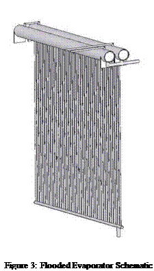
Naturally, any solar powered system requires thermal storage and it has been decided to use an ice bank integrated with the flooded evaporator of the refrigerator. Approximately 50 kg of ice is needed and this is incorporated into a vertical wall within the container. The wall has enough fins extending into the cold space so that cooling within the container is achieved by natural convection. Figure 2 shows the complete evaporator/ice-bank assembly and Figure 3 shows the flooded evaporator alone.
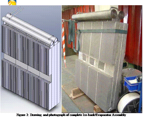 |
The evaporator consists of approx. 40 vertical half inch diameter tubes with a large reservoir above and parallel feed below. Later versions will have direct expansion evaporators which will have the advantages of lower mass, lower cost and reduced refrigerant charge, but the overwhelming advantage of a flooded evaporator is that requires less development and is comparatively risk free. Each of the vertical tubes fits tightly between the fins of an aluminium extrusion that forms part of the ice-bank. Without this heat transfer enhancement, towards the end of the process of freezing the water, the evaporating temperature would drop significantly as heat from the freezing front had
 to be conducted through an increasing thickness of ice, thereby reducing the system COP (cooling power / driving heat input).
The same aluminium extrusion is used on the outside of the ice tank to transfer heat to the cold space.
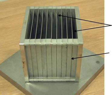
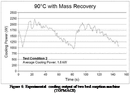
The refrigeration system is based on an adsorption cycle using ammonia as refrigerant and active carbon adsorbent. The plate heat exchanger (sorption generator) developed for this and other applications is shown in Figures 4 and 5. It is of low thermal mass (for good COP) and allows rapid cycling which reduces the physical size of the sorption generator for a given cooling power. Two of these generators, about 200mm on one side have been used in ‘TOPMACS’, an EU project to create a car air conditioning system that is driven by the waste heat of the engine. Laboratory operating results are given in Figure 6, which shows a mean cooling power of 1.6kW. The solar ice-making application is similar and design work is based on two similar but improved units. In the original generator, granular carbon in 4mm thick layers was sandwiched between stainless steel shims containing numerous water channels for heating and cooling the
carbon. The new design will utilise a more highly conductive (~2.0 W m K-1) carbon developed by ATMI
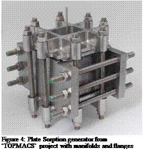 |
which will enable the use of 12mm carbon layers, reducing cost, complexity and thermal mass. The two beds will be operated in a simple cycle with both mass and heat recovery, with typical cycle times of 2 minutes.

|
|
|
|
|
 |
The original design for car air conditioning was heated or cooled by unpressurised water. The solar collectors are expected to operate at well above 100°C and so the choice had to be made between using a heat transfer fluid or pressurised water. The heat transfer properties of water are so superior that pressurised water was selected.
A schematic of the whole refrigeration system is shown in Figure 7. Hot water from the solar collectors is pumped to either G1 or G2, heating the carbon within and desorbing ammonia. The ammonia flows through a check valve to the condenser where heat is rejected, through the float type expansion valve to the flooded evaporator / ice bank, where it boils and produces useful cooling. From there it passes through a check valve and into the other generator, where it is adsorbed. It is necessary to remove the heat of desorption via another pressurised water loop to an
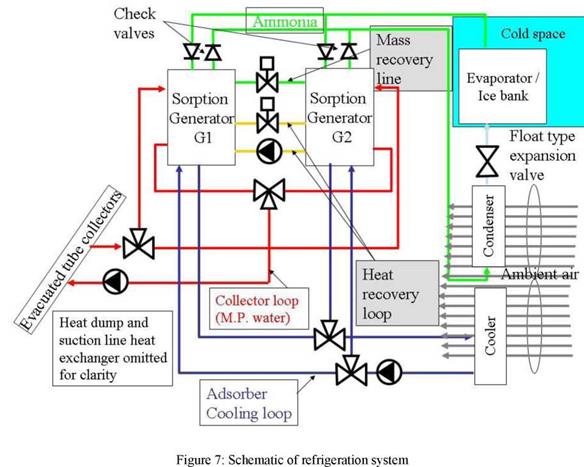 |
air cooled heat exchanger. At a suitable time (optimised for maximum cooling power) the cycle is reversed and the bed that was desorbing becomes the adsorber and vice versa. At the change-over, the performance can be improved, firstly by briefly opening the mass recovery line to equalise pressures in the two generators and then by using the heat recovery loop to pre-heat one bed with the reject heat of the other.
Given the high collector temperatures, the only commercially available options are evacuated tubes. The collectors used in our simulation models are Thermomax DF100 2m2 panels which feature direct flow of the fluid (water at up to 8 bar pressure) through the tubes. Figure 8 shows the manufacturer’s performance data. 10m2 collector area will be used to obtain a peak cooling power of up to 2 kW at an ambient temperature of 40°C in a desert environment.
A critical area of design is the waste heat rejection from the condenser and adsorbers. This is done using conventional fan coils and with attention being paid to minimising the fan power. The design compromises are critical. A small compact heat exchanger may have higher temperature differences which lead to lower COP and hence more heat to be rejected. It may also need more fan power and since parasitic electrical power will be met from PV, this must be minimised. Conversely, very large heat exchangers could be both impractical and costly. The compromise chosen uses a direct condenser measuring 650 h x 900 l x 570 w and with a 66W fan motor and a cooler measuring 650 h x 900 l x 470 w with a 102W fan motor.
|
Collector efficiency, G=1000W/m2, Tamb=40°C
Figure 8: Performance curves of chosen evacuated tube collectors |
The operation of the complete system has been modelled in Matlab to assist the design. The operation of the chiller has to be modelled at a timestep of about 0.001 s which is obviously impractical for modelling several days of operation. This problem has been overcome by deriving a pseudo-dynamic model in which the chiller is assumed to respond much more quickly (within minutes) than changes in the load or ambient conditions.
|
Figure 9 : Performance envelope for ambient temperature 30°C and evaporating temperature -10°C |
An example of the approach is given in Figure 9 in which each point (derived from detailed simulation every 0.001 s) corresponds to a balance between the heat input from the collectors at the particular insolation and ambient temperature, together with a particular cycle time (control
parameter) and evaporating temperature (corresponding to the state of the load). The envelope of the points (linear and quadratic are shown) gives the instantaneous cooling power corresponding to the best control strategy for that particular evaporating temperature and ambient temperature for the full range of insolation.
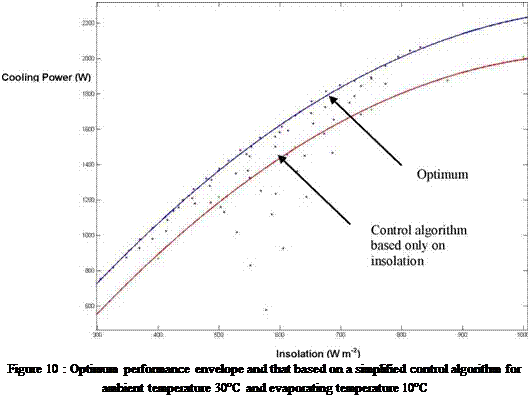
A set of these correlations for a range of evaporating and ambient temperatures may be combined empirically to yield a polynomial function for optimum cooling power under any conditions which can act as input to the model of the ice-bank and cold box. Preliminary examination of these results implies that the cycle time can be made a simple function of insolation only (i. e. ignoring ambient and evaporating temperature) with comparatively little penalty. Figure 10 illustrates this for the particular case of an ambient of 30°C and evaporating at 10°C.