Как выбрать гостиницу для кошек
14 декабря, 2021
Dirk Pietruschka1. Uli Jakob[8], Vic Hanby[9], Ursula Eicker1
1 Centre for Applied Research of Sustainable Energy Technology — zafh. net
Stuttgart University of Applied Sciences, Schellingstrasse 24, D-70174 Stuttgart, Germany
Tel.:+49/711/8926-2674, Fax: +49/711/8926-2698, Email: pietruschka@zafh. net
2 SolarNext AG, Nordstrasse 10, 83253 Rimsting, Germany
Tel.:+49/8051/6888-403, Fax: +49/8051/6888-490, Email: uli. jakob@solarnext. de
3 Institute of Energy & Sustainable Development, De Montfort University, Leicester LE1 9BH, U. K.
The performance of solar driven cooling systems strongly depends on the implemented control strategies of the absorption cooling system including the chiller, the cooling tower, the installed cold distribution system and the solar collector field [1-4]. High electricity consumption caused by suboptimal control in combination with low solar fractions through insufficient system design are critical for the environmental and economical performance of installed absorption cooling systems (ACM), especially if they are compared to highly efficient electrical driven compression chillers [1, 4]. For the control of such complex systems often different independently operating component controllers are combined in one solar cooling installation resulting in a more ore less optimal system control. To overcome these problems and to allow the implementation of advanced control strategies, the development of combined system controllers are required, which are able to control all components of a solar cooling and heating system. Such a combined system controller has been developed by the SolarNext AG in Rimsting, Germany. A detailed dynamic simulation model in INSEL [5] has been used for the development of the advanced control strategies. To ensure optimal system operation the implemented advanced control strategies have been implemented and tested in the dynamic simulation environment. In the present paper this method is demonstrated for the optimisation of the start-up process through improved storage charge management of a solar driven chillii® Solar Cooling System, which has been installed in an office building in Rimsting, Germany. The design methods used for the developed control strategies, the controller algorithms found and the results of the controller tests in the simulation environment are presented and discussed in detail.
|
|||||||
|
|
|
|
||||
|
|||||||
|
|
|
|||||
|
|||||||
 |
|||||||
|
|||||||
|
 |
||||||

 |
 |
|
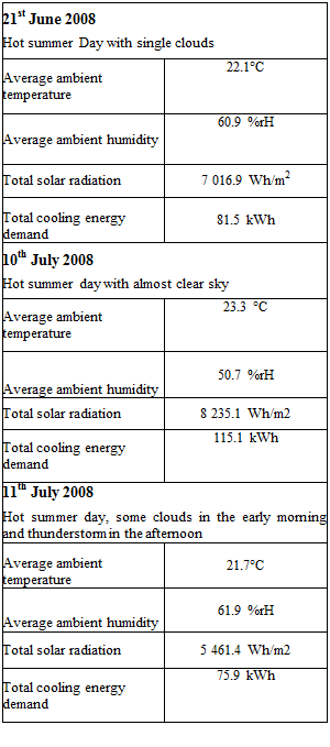
Table 2: Analysed typical hot summer days
![]()
![]()
![]()
![]()
![]()
![]()
![]()
![]()
![]()
 100
100
90
80
„ 70
О
з
го 50
q3
40
<D
H 30 20 10 0
The results for all analysed storage charge and discharge cases (case 1-4) and daily weather conditions are summarised in Table 3 and 4. If always the full storage volume is used (case 1) the start-up time of the absorption chiller varies between 11:03 and 11:38am depending on the summer day regarded. This perfectly corresponds with the commonly expected performance of solar driven absorption cooling systems. However, as a result of the late start-up 27 to 39% of the cooling load of the building can’t be covered by the system. As expected for case 1, the best results are obtained for the 10th July (cloudless day) and the worst result for the 11th July (some clouds in the early morning and thunderstorm in the early afternoon). In Case 2 with bypass of the hot storage, the start-up times can be significantly reduced by more than 1h 40 min for all of the three analysed days. The earliest start-up time of 9:23am is obtained on 10th July followed by 9:26am on 11th July and 9:40am on 21st June (single clouds). Due to the early system start-up, the cooling load which can’t be covered is also significantly reduced and varies between 11% and 14%. The partition of the storage tank in case 3 leads also to much earlier system start-up times but does not reach a higher coverage of the cooling load compared to case 2 on any of the analysed days. The best overall performance is reached for case 4 with combined bypass and partitioned storage control. Compared to case 1 the part of the cooling load which can’t be covered is reduced to 14 % (10th June), 10% (21st June) and 16% (11th July) with almost the same start-up times as in case 2. If the produced cooling energy is regarded, the advantage of the improved storage charge and discharge control in case 4 compared to case 1 becomes even more visible with 18% more cooling energy production on 21st June, 23% more cooling energy production on 10th July and 33% more cooling energy production on 11th July.
The thermal and electrical COP is very slightly influenced by the analysed storage charge and discharge control cases but is significantly influenced by the type of summer day. The highest thermal COP of the absorption chiller of 0.69 and the highest electrical COP of complete solar cooling system of 8.5 are reached on 10th July with almost clear sky due to the highest driving temperatures. For 21st June and 11th July significantly lower thermal COP of 0.64 to 0.66 and electrical COP of 7.1 to 7.7 are reached, which is mainly caused by the overall lower driving temperatures at generator inlet. The electrical COP of the solar cooling system includes the electricity consumption of all components and pumps (ACM, cooling tower (fan speed control) and
all pumps (generator, evaporator, absorber/condenser and primary and secondary collector pump), only the distribution pump and fan coils are not considered.
|
Table 3: Results Related to Heating Energy Consumption and Cooling Energy Production
Legend: Qs Solar irradiation on the collector plane (gross area) Qh, st_in Heating energy stored in the hot storage at the end of the day Qc, acm Cooling energy produced by the ACM Qc, stored Cooling energy stored in the cold storage at the end of the day Qh, st_in Solar heating energy storage input ns Efficiency of the solar system Qc, req Required cooling energy Qh acm heating energy used by the ACM |
|
Table 4: Results Related to ACM Operation
|
|
Legend:
|
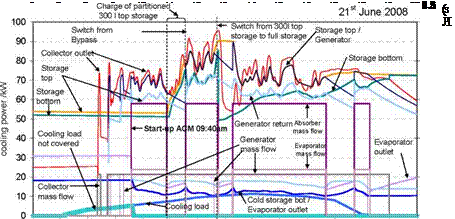 |
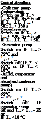
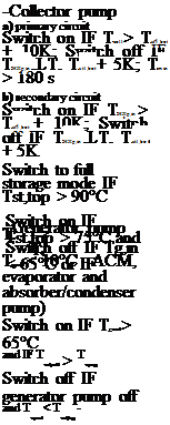
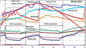
To visualise the behaviour of the developed control algorithm, one example of detailed simulation results are shown Figure 3 for the most complex control in case 4 with combined bypass and partitioned storage control for the 21st of June. This chart clearly shows the different control phases, with the start-up of the primary collector pump at 80°C collector temperature which is then switch off again due to a sudden drop of the collector outlet temperature caused by the cold water stored in the tubing. The second start up of the collector pump is also followed by a start-up of the generator pump in bypass mode which is turned off again as the generator inlet temperature drops below 65°C. The primary collector pump remains in operation since the collector outlet temperature at heat exchanger inlet is above the storage bottom temperature. The generator pump is switched on again as soon as the collector outlet temperature at heat exchanger inlet reaches 75°C. After the generator outlet temperature reaches 65°C the ACM with evaporator and absorber pump is switched on and the ACM starts to produce cold water which is fed into the cold storage tank. After more than one hour of operation the generator inlet temperature decreases below 65°C due to low solar radiation and the generator pump is switched off. The ACM with evaporator and absorber pump remains in operation as long as the evaporator outlet temperature is 1 K below the cold storage top temperature. After the generator pump is turned off, the upper part of the partitioned storage is charged by the collector and reaches a temperature above 75°C within a short time period of half an hour. Therefore, at the second start up of the ACM the control switches from bypass mode to partitioned storage mode. The ACM is then in operation until the evaporator outlet temperature decreases below 10°C which leads to a switch off of the generator pump followed by a switch off of the ACM including evaporator and absorber pump as soon as the evaporator outlet temperature is less than 1 K below the cold storage top temperature. Due to the switch off of the heating load the temperature in the upper partitioned part of the storage volume increases fast above 90°C which results in a switch from portioned storage mode to full storage mode for the rest of the day.
Figure 3: Detailed simulation results of case 4 for the 21st June 2008
Despite of the detailed analysis of the performance of the solar cooling system, the full dynamic simulation model was also very useful in the development phase of the controller algorithms. Several not obvious control errors could be detected and directly eliminated in the controller code without the necessity of time consuming on site or laboratory tests.
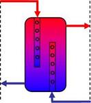
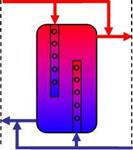
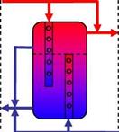
The focus of the present work is on the optimised control of solar driven absorption cooling systems for early system start-up in the morning and sufficient heat supply during operation. For the analysis of the behaviour of the developed control algorithms and their effect on the overall performance of the solar cooling system a detailed full dynamic simulation model developed in INSEL has been used. Four different control options for the storage charge and discharge control of a 15 kW chillii® Solar Cooling System installed in an office building of the SolarNext AG in Rimsting Germany have been analysed for three different typical summer days. In case 1 always the full hot water storage volume is used for the solar system, in case 2 a storage bypass is integrated for an early system start-up. In case 3 the storage is partitioned in an upper 300 l part and a lower 1700 l part and in case 4 the storage bypass is combined with a the partitioned storage tank. The developed control algorithms have been tested and improved in the dynamic simulation environment for different weather conditions. Several not obvious control errors could be detected and removed from the control code without the necessity of time consuming on site or laboratory tests. The proofed control codes of the four cases mentioned above were then used to analyse the overall performance of the solar cooling system for three different typical hot summer days. It could be shown, that through the implementation of a storage bypass the start up time can be significantly reduced by 1h 40 min in the worst and nearly 2 h in the best case. For the partitioned storage case, the start-up time is between 12 and 20 minutes later. On a cloudless summer day the start-up of the solar cooling system is at 9:23am (Bypass), 9:43am (partitioned storage) instead of 11:04am (full storage). The overall best performance is reached for case 4 with the combined bypass and partitioned storage control. If the produced cooling energy is regarded, the advantage of the improved storage charge and discharge control in case 4 compared to case 1 becomes clearly visible with 19% more cooling energy production on 21st June 2008 (day with some clouds) and 10th July 2008 (cloudless day) and 33% more cooling energy production on 11th July 2008 (some clouds in the early morning and thunderstorm in the early afternoon).
The thermal and electrical COP of the solar cooling system is only very slightly influenced by the different control modes but strongly depends on the analysed type of summer day. For a hot cloudless summer day (10th July) the thermal COP is a 0.69 and the overall electrical COP is 8.5 in the best case. Due to the lower available driving temperatures, the thermal COP is reduced on cloudy days (21st June and 11th July) to 0.64 in the worst case. The lower thermal COP results in longer operational hours at low cooling capacity and thereby reduces also the electrical COP which is 7.06 in the worst case.
References:
[1] Pietruschka, D., Jakob, U., Eicker, U., Hanby, V. “Simulation based optimisation and experimental investigation of a solar cooling and heating system”, Solar air conditioning, 2nd international conference, Tarragona, Spain, 2006
[2] Henning, H.-M. “Solar-assisted air-conditioning in buildings — a handbook for planners”, Springer — Verlag 2004, ISBN 3-211-00647-8
[3] Mendes, L. F, Collares-Pereira, M., Ziegler, F. “Supply of cooling and heating with solar assisted heat pumps: an energetic approach”, Int. J. Refrig. Vol 21, No.2, pp 116-125, 1998
[4] Kohlenbach, P. “Solar cooling with absorption chillers: Control strategies and transient chiller performance”, Dissertation Technische Universitat Berlin, 2006
[5] Schumacher, J. “Digitale Simulation regenerativer elektrischer Energieversorgungssysteme”,
Dissertation Universitat Oldenburg, 1991 www. insel. eu