Как выбрать гостиницу для кошек
14 декабря, 2021
Conventional desiccant cooling system is comprised basically of a desiccant rotor, a sensible heat rotor, and a direct evaporative cooler. In this system, the process air to be supplied to the conditioned space is first dehumidified flowing though a desiccant rotor. The process air then passes a sensible heat rotor to be cooled sensibly by transferring heat to the outdoor air. Lastly, the process air is cooled further flowing through a direct evaporative cooler and supplied to the conditioned space. However, since the air is humidified through the direct evaporative cooler, the process air needs to be dehumidified at the desiccant rotor that much more in addition to the dehumidification for the latent load removal. This causes a large dehumidification load of the desiccant rotor and subsequently large thermal energy input to regenerate the desiccant rotor to deteriorate the thermal efficiency of the system.
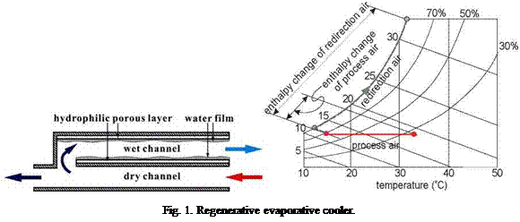
Meanwhile, it is known that the air can be cooled evaporatively without an increase in the humidity in a regenerative evaporative cooler (REC)[4-8]. Basically, the REC is comprised of a pair of dry and wet channels as shown in Fig. 1(a). The process air flowing through the dry channel is cooled down by transferring heat to the adjacent wet channel. At the outlet end of the channel, a portion of the air is extracted and redirected to the wet channel, while the remaining portion is supplied to the air conditioning space. The extracted air flows through the wet channel in the opposite direction to the air stream in the dry channel and becomes colder than the process air in the dry channel due to the water evaporation from the wet surface. The temperature difference between the channels then causes heat removal from the dry channel to cool the process air stream. The air flowing out of the wet channel is exhausted to the outdoors. This cooling process is summarized in a psychrometric chart, Fig. 1(b). It is seen that the specific enthalpy change of the wet channel air flow is much larger than that of the dry channel air flow. For the energy balance between the channels, 1/5~1/3 of the process air is enough for extraction to the wet channel and the rest of the process air can be supplied to the conditioned space.
 |
As can be inferred from Fig. 1(b), the REC is able to cool the incoming air down to its inlet dewpoint temperature even without an increase in the humidity. Consequently, when applying the
(a) schematic of the regenerative evaporative cooler (b) psychrometric chart
Fig. 2. Desiccant cooling system incorporating a regenerative evaporative cooler.
REC instead of the DEC, the humidity of the air at the inlet of the evaporative cooler dose not need to be so low as that in the system with a DEC to get the same outlet temperature. This fact implies that a substantial decrease in the dehumidification load of the desiccant rotor can be achieved by applying a REC.
Figure 2 shows the schematic of the desiccant cooling system with a REC and the corresponding psychrometric chart. The basic configuration of the desiccant cooling system with a REC is the same as the system with a DEC except for the application of the REC instead of the DEC. Incorporating a simple direct evaporative cooler at the end of the REC can reduce further the supply air temperature by 2 or 3oC.
In this study, a prototype of the desiccant cooling system incorporating a regenerative evaporative cooler was designed, fabricated and tested for the performance evaluation. The prototype was designed to show 4 kW cooling capacity at the ARI condition (indoor: 27oC, 50%RH, outdoor: 35oC, 40%RH) with the hot water supply of 70oC as the heat source. The ventilation ratio was determined to be 0.3, that is, the supply air comprises of 30% outdoor air and 70% recirculation air. To this purpose, two important components, i. e., the regenerative evaporative cooler and the desiccant rotor were developed and tested before being assembled into the system.