Как выбрать гостиницу для кошек
14 декабря, 2021
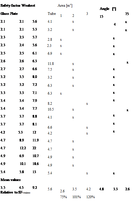
For making it easier to see any general trends about what are a good and a less good construction, a compilation of the safety factors and the varied parameters were made, which can be seen in table 4.
In the upper part of the table each row shows the safety factors of one solar collector. The x-marks describe the configuration. In the lower part of the table, the mean values for each column is presented. For the columns describing configuration, the mean values are the averages of the SFweakest of the x — marked rows. The last row shows the quotients between each column’s mean value in relation to the mean value of SFweakest.
 |
|
Two parameters show significant importance to the safety factor. The important factors are area and angle. for setting figures of the impact of the parameter a trend analysis was done. The formula of the mean safety factors dependence of the area is expressed in (6)
N. B. the matrix of input data for the areas and angles were centered in order to keep a low condition number. They were also divided with maximum deviation in order to make them easier comparable.
|
|
 |
|
 |
The purpose of this work was using commonly used dimensions and materials when building collectors. However, there are variations in almost all dimensions between different commercial collectors, and when trying to keep down the analysis data some of the factors where set constant.
The shape and design of the connection between glass and absorber has influences on the stresses in the materials, especially in the connections. In the absorber there is no maximum of stresses in the connection points. This makes the maximum stresses trustworthy also in other designs, at least when the stresses can be distributed in a less concentrating way at the connection point. In the glass the case is the opposite since the maximum of stresses is in the connection to the absorber. This makes probably the maximum of stress in the glass in this article dependant on the choice of connection. And our speculation is that the maximum stress in the glass always will be a question of how the connection is designed, i. e. the maximum of stresses in the absorber is more or less universal while it is not that for the glass.
There are numerous parameters influencing the strength of a gas filled solar collector. The most obvious parameters are the distance between glass and absorber, the area of the absorber and the angle build by arctan(width/height). The safety factor increases with low angles (long tubes), big areas and small distances.
It is not clear to the same extent about selection of material, thicknesses etc. If you take a look again at table 4 and make a comparison between the 3 and 4 mm glass respectively on the 2 m2, 45°, absorber plate in aluminium, you can see that the one with a thicker glass has a smaller safety factor. By choosing a thicker glass the safety factor of glass raise, but at the same time the safety factor for the tubes goes down and will be the weakest safety factor. Therefore, a strengthening of one part can punish itself if it is too big.
There are no special restrictions of either using Copper or Aluminum in the collector. Here we only examined 0.5 mm Aluminum and 0.25 mm Copper, due to thermal demands.
The stresses in the glass are affected by the connection to the absorber. When using other connections the calculations have to be redone.
|
Nomenclature
min Minimum |
[1] M. F. Ashby, and D. R.H. Jones, (1998), Engineering Materials 1, 2 edn, 0 7506 3081 7, Butterworth — Heinemann.
[2] B. Sundstrom, (1998), Handbok och formelsamling Hallfasthetslara (Hand book and formula collection in mechanics of materials), 2 edn, Institutionen for hallfasthetslara KTH, Sodertalje.
[3] N. Khorasani, Design Principles For Glass Used Structurally, (Lunds universitet), pp 79, ISSN 1103-4467, 2004
[4] S. Sunnersjo, (1992), FEM i praktiken (FEM in practice), 2 edn, 91-7548-541-9, Industrilitteratur AB, Uddevalla.
[5] J. A. Duffie, and W. A. Beckman, (1991), Solar engineering of thermal processes, First edn, 0-471-51056-4, John Wiley & Sons, Inc.