Как выбрать гостиницу для кошек
14 декабря, 2021
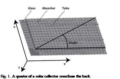
All calculations started out from common used design, dimensions and material of existing collectors. Sizes of 1 to 3 m2 were examined and different relations between length, width and height were investigated. The used directions of x, y and z can be seen in figure 1. The collector model consisted of a sheet of glass and an absorber formed as a tub where the edge of the tub was fixed on the glass sheet. The connection between glass and absorber in the model was the simplest possible where the absorber mesh was connected to the glass mesh as a "T" in an imagined cross section. The cavity was the volume between glass and absorber. All folds in absorber had a radius of 5 mm. The glass was sticking out 40 mm outside the absorber tub. 12 mm tubes with 0.85 mm material thickness were supposed to be placed on the backside of the absorber with a centre distance of 120 mm.
 |
Material properties comes from soda glass, copper and aluminium. A complete list of used conditions can be seen in table 1.
|
Table. Physical properties and geometries used in the mathematical model.
|
2.1. Calculations
The Solar collector box had known dimensions, and it was possible calculate the volume enclosed by a list of faces (Venclosed) at different pressures. We supposed that when T=300K, the pressure inside
and outside of the box is 100kPa and all stresses in the material is 0. Then we wanted to find a P when T=500K. We used the ideal gas law for finding the pressure and volume at the new temperature.
 |
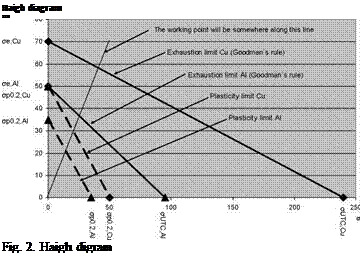
Estimations of fatigue were made for having an understanding of if the stresses will imperil the function of the expected lifetime of the construction. A Haigh diagram, which can be seen in figure 2, is a help when doing valuations of fatigue.
The stresses are divided in to a static and a dynamic part. The static stress is put on the x-axis and dynamic stress on the y-axis. We use Goodman’s rule as the limit between the safe and the unsafe area[1]. Goodmans rule can be seen in (1).
Vtjts
The Goodman’s rule will give an line between (oUTs,0) and (0,oe) in the Haigh diagram. Plastic deformation is also unwanted; therefore a line representing that is added as an additional limit. The smallest value from Goodman’s rule and the plastic deformation line is then used as the safe area. [2]. The formula of the plastic deformation line can be seen in (2).
![]() ^ a, p0.2,allow ^ m, p0.2,allow ^p0.2
^ a, p0.2,allow ^ m, p0.2,allow ^p0.2
The plastic deformation limit will be a line between (op0.2, 0) and (0, op0.2). This means that the limit is op0.2 no matter the proportions between dynamic and static stress which gives us the allowable stress expressed as in (3).
![]() ^T 500, allow ^T 500,p0.2 ^p0.2
^T 500, allow ^T 500,p0.2 ^p0.2
With table values of Copper and Aluminium, the maximum allowable stresses will become as in table 2 [2].