Как выбрать гостиницу для кошек
14 декабря, 2021
 After having introduced the procedure for mirror deformation reproduction, the first study examines the consequences produced by the deformations of a solar trough collector. The study is based on the use of ray tracing analyses that allow controlling all the optical parameters. Considering the application of sunlight exploitation, the most important features probably are collection efficiency, angular aperture and acceptance angle. The collection efficiency E is the ratio between the light focused on the absorber and the light received by the collector entrance aperture. The angular aperture of a collector represents the total aperture angle receiving the sunlight rays and it is usually expressed as Field Of View (FOV). While the acceptance angle is the limit aperture for which the collection efficiency keeps its maximum value. The angular analyses of the solar trough collector are discussed in Sections 4-5.
The collection efficiency of solar trough has been monitored in order to evidence how much it is affected by the geometrical deformation of mirror profile.
The configuration considered in this study is characterised by the following parameters: f=780mm, D=50mm,
G=70mm, T=2mm. The absorber centre is located in the focal point of the parabolic mirror.
The simulations are carried out for various values of the conic constant K,
corresponding to elliptic and hyperbolic Fig. 3. Deformation effects versus wrtiral
edge displacement.
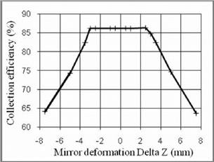
deformations. The results are graphically reported in Fig. 3, whose calculation parameters are detailed in Table 1. The sampling for the conic constant K (Column 2) is not linear because we preferred to choose as reference parameter the deformation at the mirror extreme. The reference quantity chosen to represent the mirror deformation is the vertical displacement of mirror extreme Delta Z, reported in Column 6 of Table 1.
Column 1 indicates the deformation type (specifying the curvature direction of the deformation with reference to Fig. 2): elliptic (internal/up) or hyperbolic (external/down). Then Column 2 reports the value of each corresponding conic constant K.
The successive three columns of the table refer to the geometrical parameters of every deformed profile. Referring to Fig. 2, the point of mirror extreme has as coordinate (Ymax; Zmax), respectively reported in Column 3 and Column 5. Still referring to the semi-profile, half of the length of each deformed profile is in Column 4, confirming that the rigid deformation is calculated keeping almost unchanged the total length of the mirror. The calculation is approximated considering only integer values of mirror semi-aperture Ymax.
|
Table 1 — Effect of mirror deformations.
|
Finally the effect of mirror deformations is reported in Column 7 as collection efficiency values; the calculation has been carried out with linear sampling in Delta Z. Figure 3 visualises the variations of collection efficiency as a function of the mirror deformation parameter Delta Z.
The sign of the Delta Z values reported in Table 1 is in agreement with Fig. 2: the vertical edge displacement is positive in the elliptic case (int./up in Fig. 2) and is negative in the hyperbolic case (ext./down in Fig. 2).
In conclusion for the examined trough collector the effect of elliptic deformations is significant only for vertical edge displacement Delta Z > 2.5 mm.
While in the hyperbolic deformation case the effect of solar trough deformations is considerable only for absolute values of Delta Z > 3 mm.